
Electrically actuated variable pressure control system

a variable pressure control and actuator technology, applied in the direction of valve operating means/releasing devices, mechanical equipment, applications, etc., can solve the problems of system drift, inefficiency, damage to nearby properties, environment and people, etc., to increase flow resistance, increase flow resistance, and reduce flow resistance

Inactive Publication Date: 2006-12-07
CAPSTAN
View PDF50 Cites 113 Cited by
  • Summary
  • Abstract
  • Description
  • Claims
  • Application Information

AI Technical Summary

Benefits of technology

[0019] The component parts of the system are simple and economical to manufacture, assemble and use. Other advantages of the invention will be apparent from the following description and the attached drawings, or can be learned through practice of the invention.
[0041] Also in this aspect of the invention, the method further includes increasing flow resistance when the sensed pressure is too low.
[0042] In this aspect of the invention, decreasing a duty cycle of a square wave increases flow resistance.
[0043] Further in this aspect of the invention, the method includes decreasing flow resistance when the sensed pressure is too high.
[0044] In this aspect of the invention, increasing a duty cycle of a square wave decreases flow resistance.

Problems solved by technology

However, a disadvantage with many spray systems relates to the drift of spray particles and droplets away from their intended targets.
Such drift is at best inefficient, as in the case of the overspray which represents wasted spray material, and in more serious situations can cause damage to nearby property, environment and people.
Notwithstanding the substantial advantages of agricultural spraying applications of pesticides and other spray materials, agricultural spraying is generally a relatively inefficient process.
Factors which contribute to such inefficiencies include the susceptibility of sprayed materials to wind drift, overspray and inaccurate placement on the intended target crop plants.
Irregularities in terrain and nonuniform plantings also contribute to the inconsistent and inefficient application of agricultural spray materials.
Moreover, variations in ambient conditions such as wind, humidity levels and temperature tend to reduce the uniformity and efficiency with which spray materials are applied to their intended crop targets.
In addition to the inefficiencies associated with misdirected agricultural spray materials, overspray and spray drift can create significant problems if the materials are inadvertently applied to adjoining areas for which they were not intended.
Such misapplication of agricultural spray materials can result in crop damage, injury to livestock, contamination of environmentally-sensitive areas and unnecessary human exposure to toxic materials.
The problems associated with the misapplication of agricultural spray materials are exacerbated by the use of larger spraying equipment covering wider swaths, high speed vehicles, air-blast spraying, and by aerial spraying.
Spray droplet size has been shown to significantly affect both the efficacy of pesticide treatments and the potential for off-target spray movement.
Conversely, such droplet mobility associated with smaller droplet sizes can exacerbate problems associated with spray drift away from application sites.
However, altering the liquid pressure also generally alters the droplet size, thus effecting the deposition and its susceptibility to spray drift, evaporation, etc.
The boundaries for such differential application rate spray zones can be irregular, with such irregularities increasing the difficulty of manually altering spray system operating conditions by an on-board operator.
Moreover, problems can arise due to operator reaction times when changed field conditions call for adjustments to the spray conditions.
For example, if an operator is alerted that he or she has crossed a field boundary or property line and initiates a procedure for altering spray application, most spray control systems have an inherent delay which may cause overspray problems.
However, the application control provided by the Ortlip apparatus occurs only along the direction of travel and not along the boom section.
Moreover, the Ortlip, apparatus does not provide for droplet size control, drift control or spray transport modeling for spray liquid deposition prediction.

Method used


Image

  • Electrically actuated variable pressure control system
  • Electrically actuated variable pressure control system
  • Electrically actuated variable pressure control system

Examples


Embodiment Construction

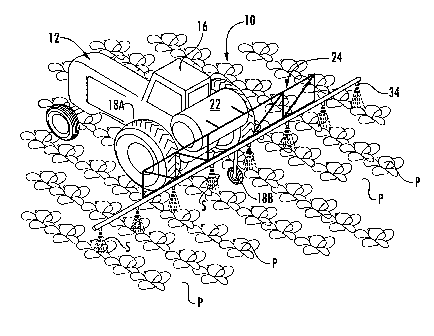
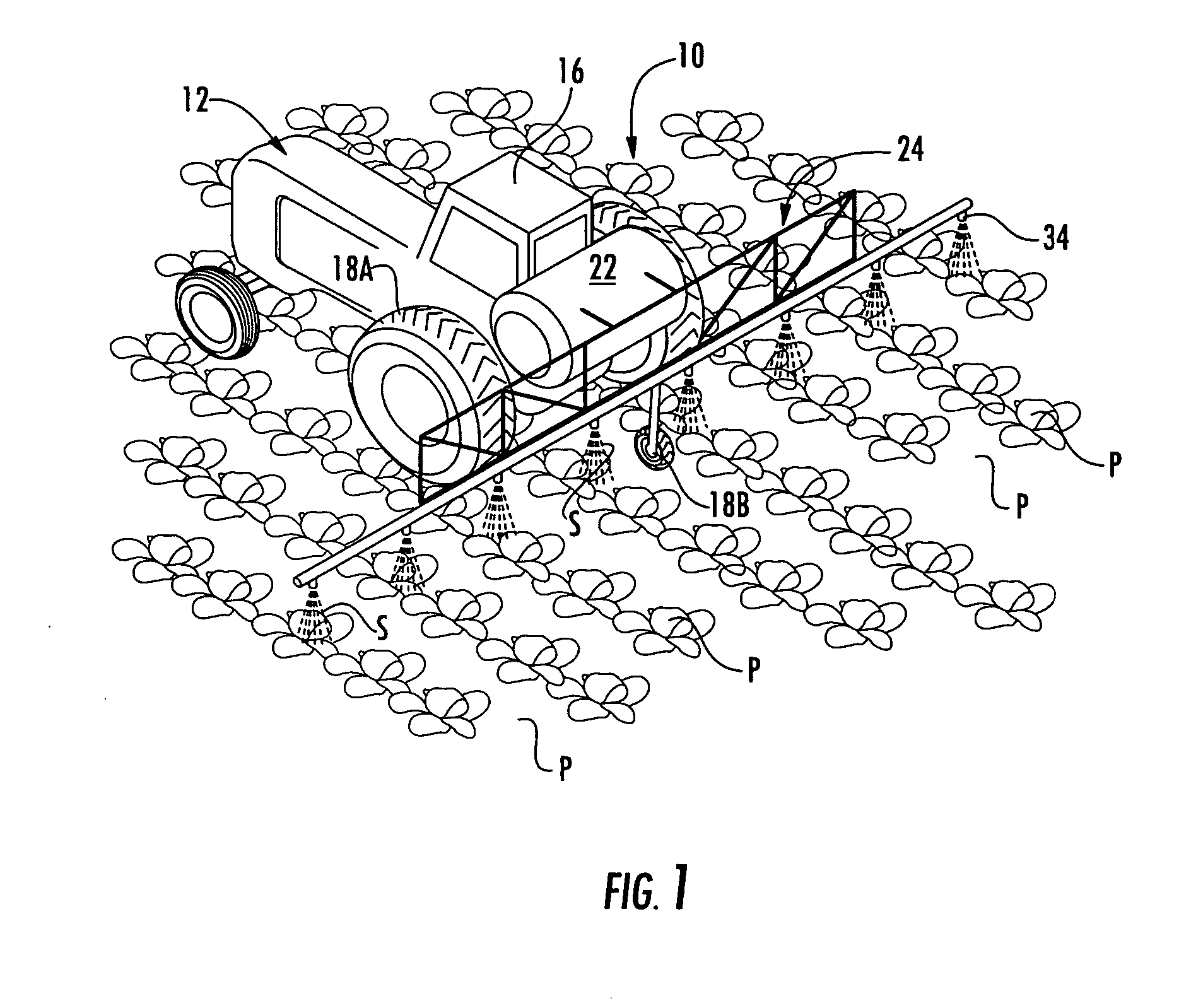
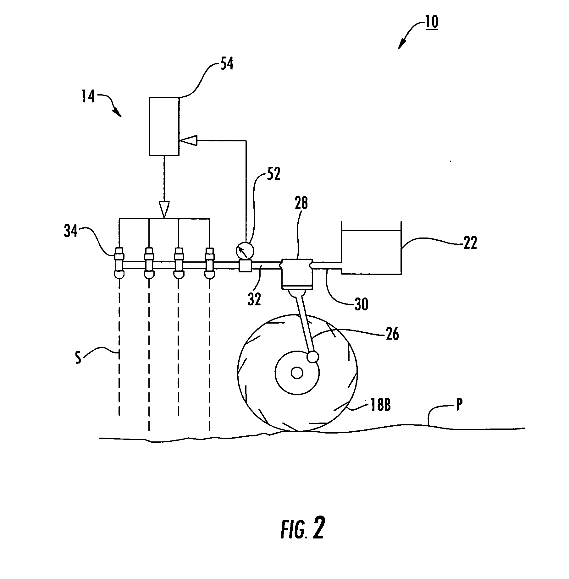
[0055] Detailed reference will now be made to the drawings in which examples embodying the present invention are shown. The detailed description uses numerical and letter designations to refer to features of the drawings. Like or similar designations of the drawings and description have been used to refer to like or similar parts of the invention.

[0056] The drawings and detailed description provide a full and written description of the invention, and of the manner and process of making and using it, so as to enable one skilled in the pertinent art to make and use it, as well as the best mode of carrying out the invention. However, the examples set forth in the drawings and detailed description are provided by way of explanation only and are not meant as limitations of the invention. The present invention thus includes any modifications and variations of the following examples as come within the scope of the appended claims and their equivalents.

[0057] As broadly embodied in FIGS. ...


PUM


Abstract

An electrically-actuated variable pressure control system for use with flow-controlled liquid application systems. Direct acting solenoid valves are pulsed at varying frequencies and duty cycles to change the resistance to flow encountered by the flow-controlled liquid application system. This pulsing solenoid valve technique preserves a high degree of accuracy and uniformity through a wide range of pressure control. This wide range of pressure control indirectly allows the flow-controlled liquid application system to operate over a wider range of flow control, yielding indirect benefits to performance and productivity. When the solenoid valves are attached to pressure-atomization spray nozzles, control over spray pattern and droplet size is further achieved.

Description

CROSS-REFERENCE TO RELATED APPLICATIONS [0001] This application claims benefit of U.S. Provisional Patent Application Ser. No. 60 / 688,259, filed Jun. 7, 2005.BACKGROUND OF THE INVENTION [0002] Spraying is a well-known method of applying a wide variety of bulk materials, primarily in liquid or a mixture of liquid and powder in a fluid propellant medium. Such spray materials can be dispensed in air currents, under liquid pressure, by gravity flow, or with any other suitable discharge means. [0003] Spray application of bulk materials offers many potential advantages, including efficiency, uniformity of coverage and flexibility to adapt spraying equipment to various conditions unique to the objects being sprayed and their particular environments. [0004] However, a disadvantage with many spray systems relates to the drift of spray particles and droplets away from their intended targets. Such drift is at best inefficient, as in the case of the overspray which represents wasted spray mater...

Claims


Application Information

Patent Timeline
IPC IPC(8): A01G27/00A01G25/09B05B9/00B05B9/03
CPCB05B1/08B05B9/0413B05B9/0423B05B9/06A01G25/16B05B12/085F16K31/0655
Inventor GRIMM, JEFFREY JOHNHENDERSON, GRAEME W.
Owner CAPSTAN
Learn More