Multi-media rotary union

a rotary union and multi-media technology, applied in the direction of hose connections, couplings, manufacturing tools, etc., can solve the problems of increased wear on the interfacing seal surface, unsuitable for use, and unsuitable finished parts, so as to prevent undesirable leakage of media, reduce the number of parts, and reduce the effect of balance ratio

Active Publication Date: 2006-12-07
DEUBLIN
View PDF29 Cites 18 Cited by
  • Summary
  • Abstract
  • Description
  • Claims
  • Application Information

AI Technical Summary

Benefits of technology

[0010] A further object of the present invention is a rotary union having a single media inlet and a single secondary seal member which results in a compact union having a reduced number of parts.
[0011] In the absence of external forces, such as those that could be generated by a spring on the non-rotating seal member, the geometry of the present invention maintains a predetermined balance ratio between 0.5 and 0.67 between the rotating and non-rotating seal faces of the primary seal assembly. When incompressible media, such as water-based or oil-based coolant is utilized, the resultant net force engages the non-rotating seal surface with the rotating seal surface in the operated, pressurized condition. Because incompressible media are generally liquid, the incompressible media serves to lubricate the interfacing seal surfaces and prevent dry running. The engaged seal surfaces prevent undesirable leakage of the media. Although U.S. Pat. No. 6,508,472 makes reference to a balance ratio, this known prior art does not suggest a particular range of balance ratios to enable a rotating union to conduct different media in the manner and structure as described in the present invention.
[0012] The outside diameter and the inside diameter of the face seals of the rotating and non-rotating seal of the primary seal a

Problems solved by technology

Another application of a rotating union involves the high-speed machining of special heat-treated steels, wherein the cutting tool may become so hot that a water-based or oil-based coolant would result in thermal shock of the cutting tool.
A third application of a rotating union involves the machining of certain medical components, where contact with a lubricating medium would render the finished part unfit for use.
The running condition results in increased wear on the interfacing seal surfaces, particularly at high rotational speeds, and extended periods of dry running operation will cause severe damage to the seal members, thereby requiring replacement of some or all of the rotating union.
However, single-inlet “pop off” rotating unions ha

Method used


Image

  • Multi-media rotary union
  • Multi-media rotary union
  • Multi-media rotary union

Examples


Embodiment Construction

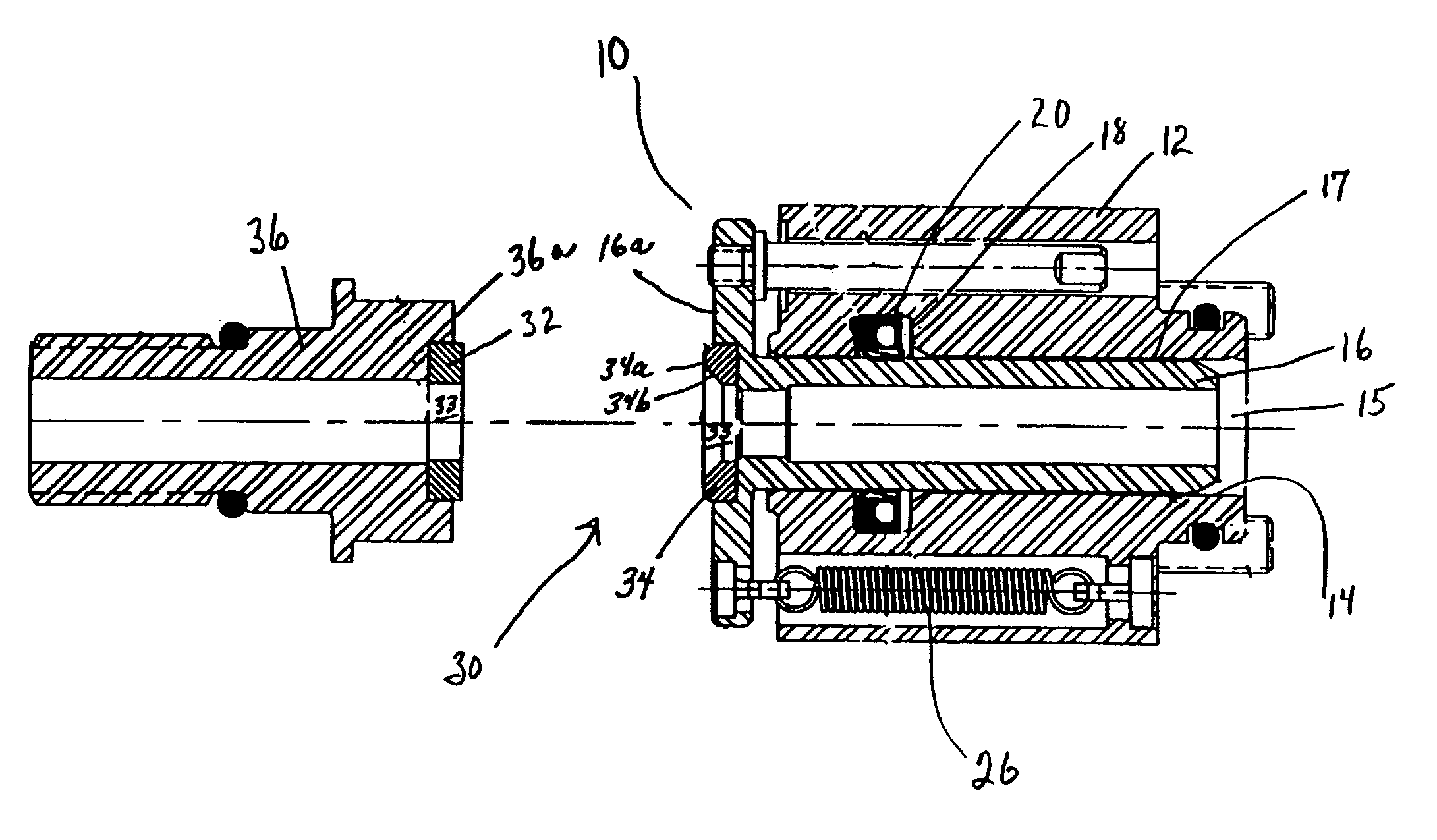
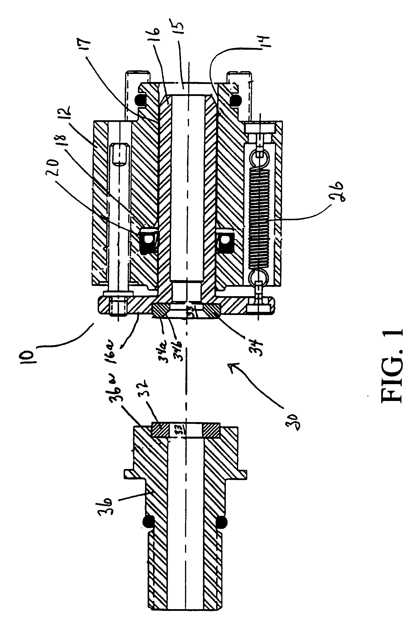
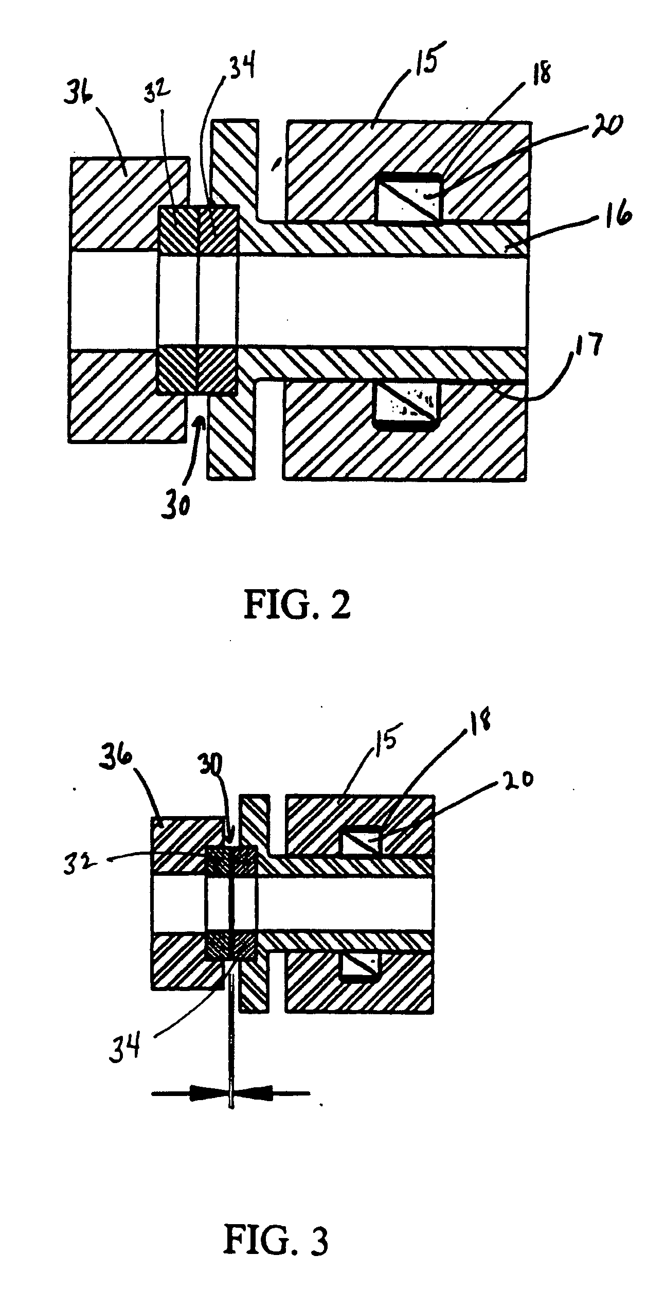
[0030] Referring now to the drawings wherein like numerals have been used throughout the several views to designate the same or similar parts, there is illustrated in the drawings a multi-media coolant rotary union or coupling device 10 incorporating a primary seal assembly 30 and a secondary elastic seal member 20 in accordance with several embodiments of the present invention. The rotary union 10, as partially shown in the drawings, is utilized to conduct incompressible media, such as water or oil-based coolants, or compressible media, such as air or gas coolants from a source of coolant to a spindle or rotor 36 of a machine tool and the like, not shown. The spindle or rotor 36 could be a machine tool used in various applications such as machining centers, flexible transfer lines or any environment where either liquid or air-based fluid coolants may be used in conjunction with the rotary union 10.

[0031] The rotating union 10 is comprised of a housing portion 12 having a cylindric...


PUM


Abstract

A rotating union communicates with a rotor member and is operable with either compressible or incompressible coolant media that enters the union through a media inlet. The union includes a housing having a counterbore and a tubular carrier member axially moveable in the housing. The union includes a primary seal assembly having a rotating seal member mounted to the rotor member and a non-rotating member mounted to the carrier member and a secondary seal member positioned about the carrier member. The range of the balance ratio of the primary seal assembly is disclosed when the primary seal assembly has imposed upon it a closing force, an opening force or no force.

Description

BACKGROUND OF THE INVENTION [0001] The present invention relates to fluid coupling devices such as rotating unions and, more particularly, to an improved seal design that permits a coupling device, having a single inlet passageway and latching external means of lubricating the sealing surfaces used therein, to be operated with lubricating media, such as water-based or oil-based coolants, with non-lubricating media, such as dry air and gases, and with no media of any kind. [0002] Rotating unions are known alternately as fluid couplings, coolant unions, or rotary joints and are employed in high-speed drilling and boring transfer operations, in high-speed machine tool spindles and in other operations where it is necessary to transfer a fluid medium to a rotating device. To optimize the operation of high-speed machine tools, rotating unions are required to conduct either a liquid, such as a water-based or an oil-based coolant, or a dry gas, such as air, from a source of the particular c...

Claims


Application Information

Patent Timeline
IPC IPC(8): F16L55/00
CPCF16L27/082B23Q11/103F16L27/08F16J15/16F16J15/34F16L37/00
Inventor FORD, SCOTT K.SACRAMENTO, ANTHONY R. JR.
Owner DEUBLIN
Why Eureka
Try Eureka