Image processing apparatus, liquid crystal display apparatus, and color correction method
- Summary
- Abstract
- Description
- Claims
- Application Information
AI Technical Summary
Benefits of technology
Problems solved by technology
Method used
Image

Examples
first embodiment
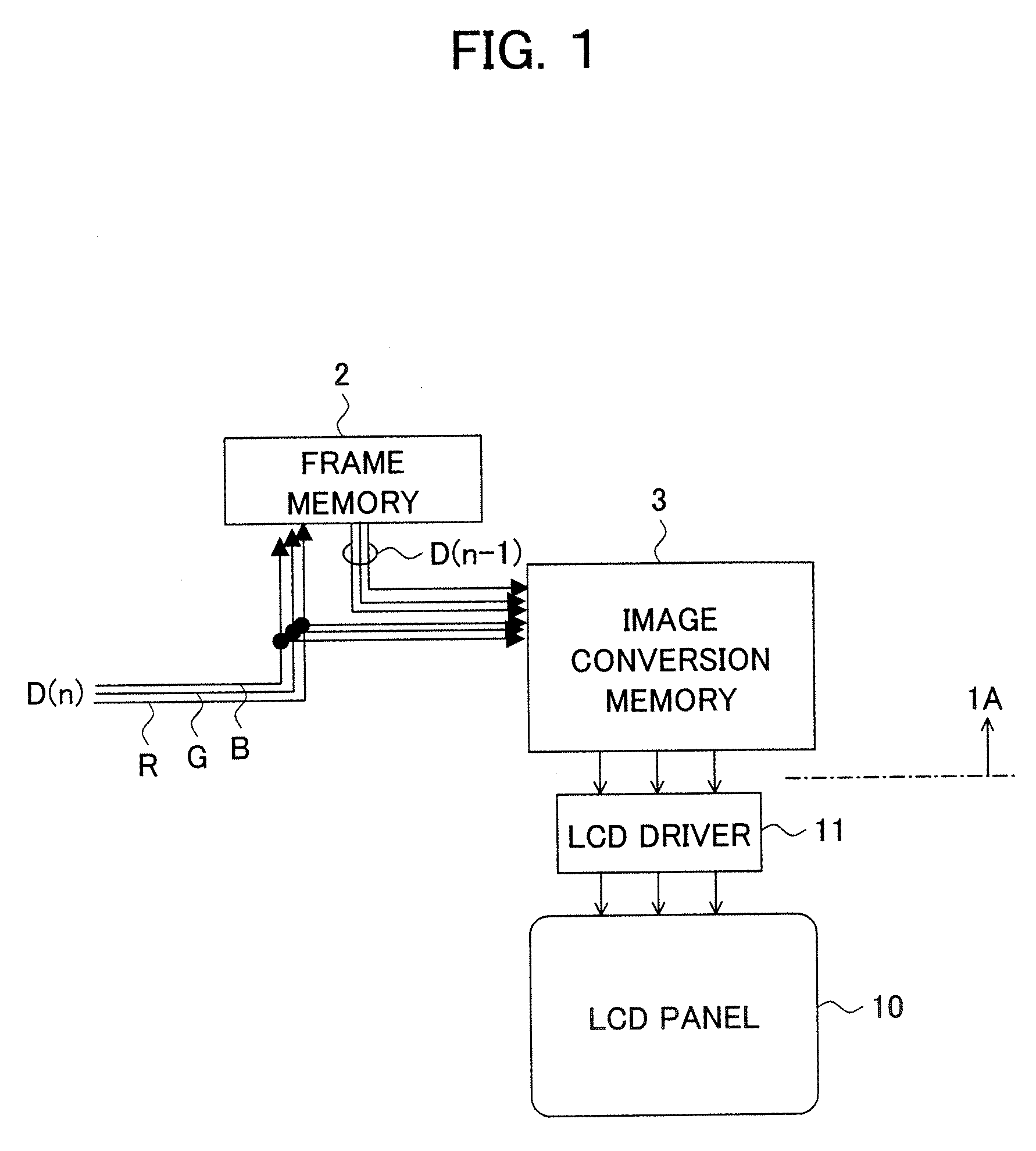
[0040]FIG. 1 illustrates a block diagram of an image processing apparatus of the first embodiment.
[0041] The image processing apparatus 1A of the first embodiment is provided with a frame memory 2 as a storage portion and an image substitution memory 3.
[0042] The frame memory 2 receives as input a current frame image data D(n) to be corrected, delays the same by one frame display period, and outputs the delayed image as a previous frame image data D(n-1).
[0043] The image conversion memory 3 can be realized by, omitted in the drawing, for example an image conversion table for the first correction mode (first image conversion table), an image conversion table for the second correction mode (second image conversion table), and a selection table for selecting one of the first image conversion table and the second image conversion table. The image conversion memory 3 may be provided with the image conversion tables for each color to be corrected for example a human skin color such as ...
second embodiment
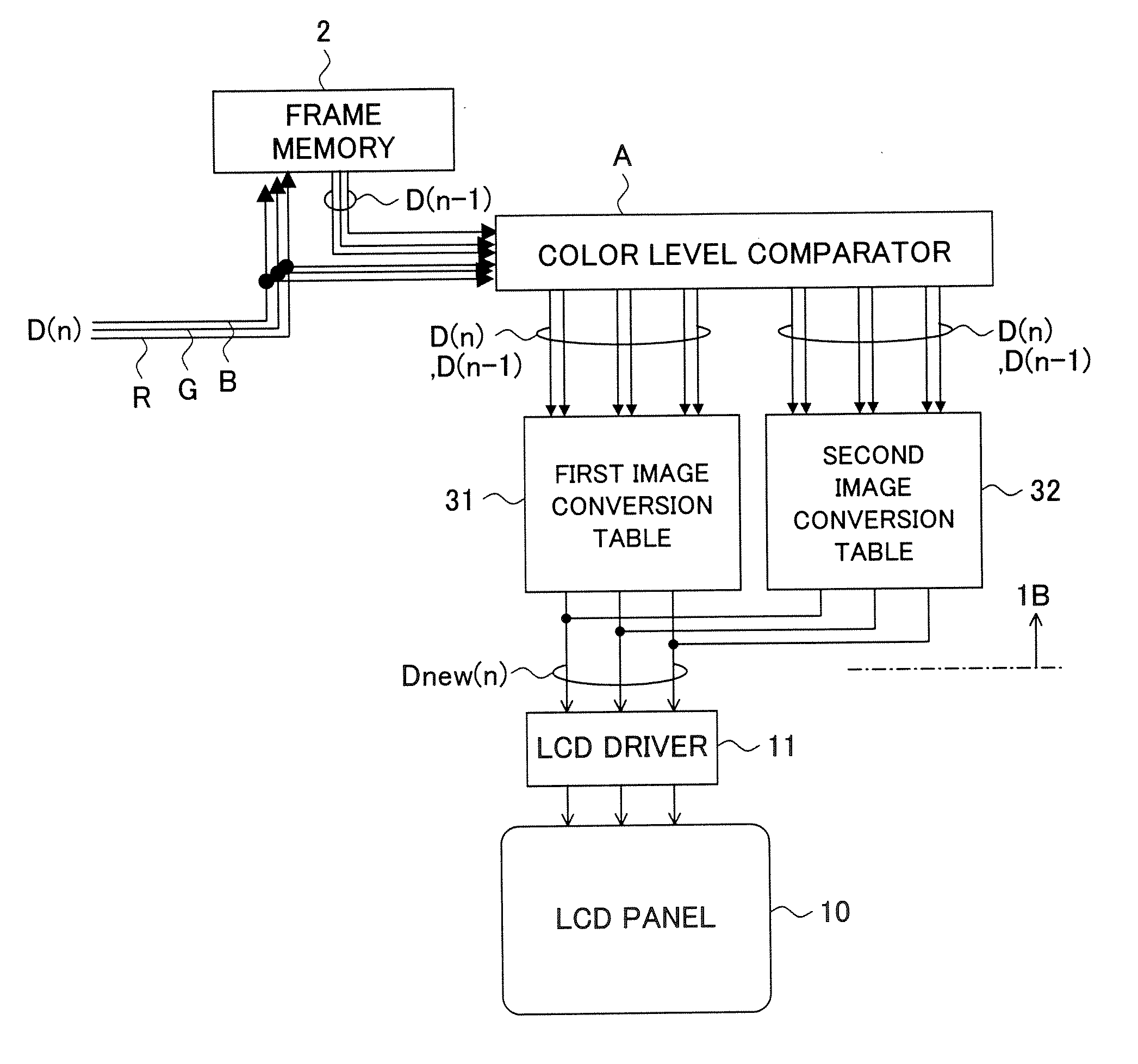
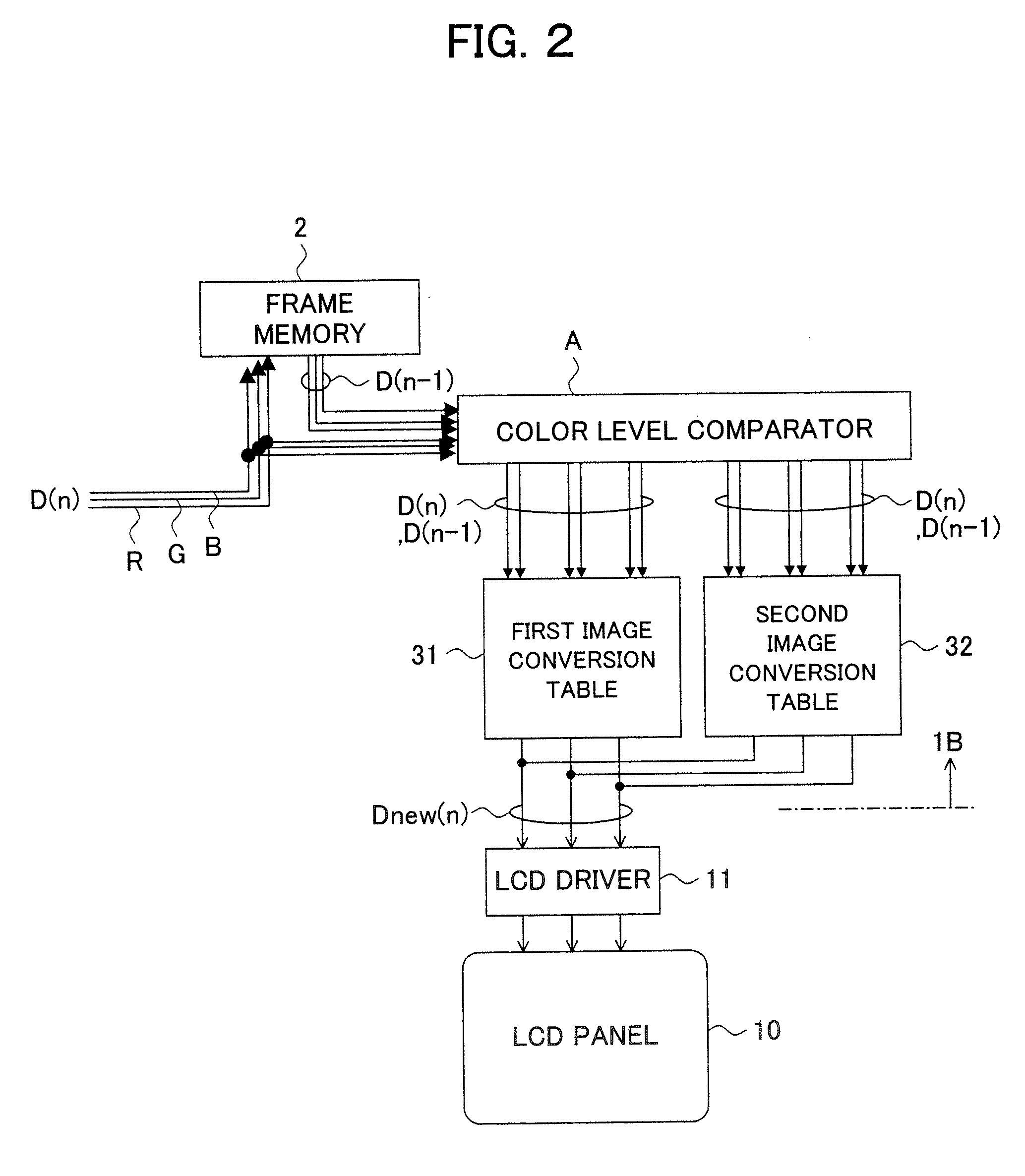
[0051]FIG. 2 is a block diagram of an image processing apparatus of the second embodiment.
[0052] An image processing apparatus 1B of the second embodiment is provided with the frame memory 2 and additionally a color level comparator 4 as a mode switch portion, a first image conversion table 31, and a second image conversion table 32.
[0053] The color level comparator 4 receives as input the previous frame image data D(n-1) and the current frame image data D(n) in units of the pixel trio of RGB, compares the signal levels of the previous frame image and the current frame image for each color, and detects whether or not an image transition is a change to the color to be corrected or that a possibility, where a change of the signal level of a color except for a specified color is delayed in the image transition to thereby cause the specified color to be emphasized, is included based on an amount of change of the signal level and a range of the signal level for each color. Further, bas...
third embodiment
[0062]FIG. 4 is a block diagram of an image processing apparatus of the third embodiment.
[0063] An image processing apparatus 1C of the third embodiment is provided with the frame memory 2, a color level comparator 4A, and additionally a first correction amount table 51, a difference correction amount table 50, a red color (R) adder-subtracter 6r and a red color (R) adder 7r, a green color (G) adder-subtracter 6g and a green color (G) adder 7g, and a blue color (B) adder-subtracter 6b and a blue color (B) adder 7b.
[0064] The color level comparator 4A receives as input the previous frame image data D(n-1) and the current frame image data D(n) in units of the pixel trio of RGB, compares the signal levels between the previous frame image and the current frame image for each color, and detects whether or not a image transition includes the change to the color to be corrected or that a possibility, where a change of the signal level of a color except for a specified color is delayed in...
PUM
 Abstract
Description
Claims
Application Information
 - R&D
- Intellectual Property
- Life Sciences
- Materials
- Tech Scout
- Unparalleled Data Quality
- Higher Quality Content
- 60% Fewer Hallucinations
Browse by: Latest US Patents, China's latest patents, Technical Efficacy Thesaurus, Application Domain, Technology Topic, Popular Technical Reports.
© 2025 PatSnap. All rights reserved.Legal|Privacy policy|Modern Slavery Act Transparency Statement|Sitemap|About US| Contact US: help@patsnap.com