Hydrogen producing apparatus utilizing excess heat from an industrial facility

a technology of industrial facilities and hydrogen production apparatus, which is applied in the field of concentrated hydrogen production apparatus, can solve the problems of requiring fossil fuels as energy sources, requiring substantial and useful hydrogen gas creation from microorganisms, and requiring large quantities of hydrogen by microorganisms

Inactive Publication Date: 2006-12-07
FELDER MITCHELL +2
View PDF46 Cites 20 Cited by
  • Summary
  • Abstract
  • Description
  • Claims
  • Application Information

AI Technical Summary

Benefits of technology

[0013] It is a further object of the invention to provide an apparatus that includes a bioreactor readily combinable and proximate with wide variety of industrial facilities of differing ...

Problems solved by technology

Similarly, steam reforming is another expensive method requiring fossil fuels as an energy source.
Substantial and useful creation of hydrogen gas from micro-organisms, however, is problematic.
The primary obstacle to sustained production of useful quantities of hydrogen by micro-organisms has been the eventual stoppage of hydrogen production generally coinciding with the appearance of methane.
As ...

Method used


Image

  • Hydrogen producing apparatus utilizing excess heat from an industrial facility
  • Hydrogen producing apparatus utilizing excess heat from an industrial facility
  • Hydrogen producing apparatus utilizing excess heat from an industrial facility

Examples


example 1

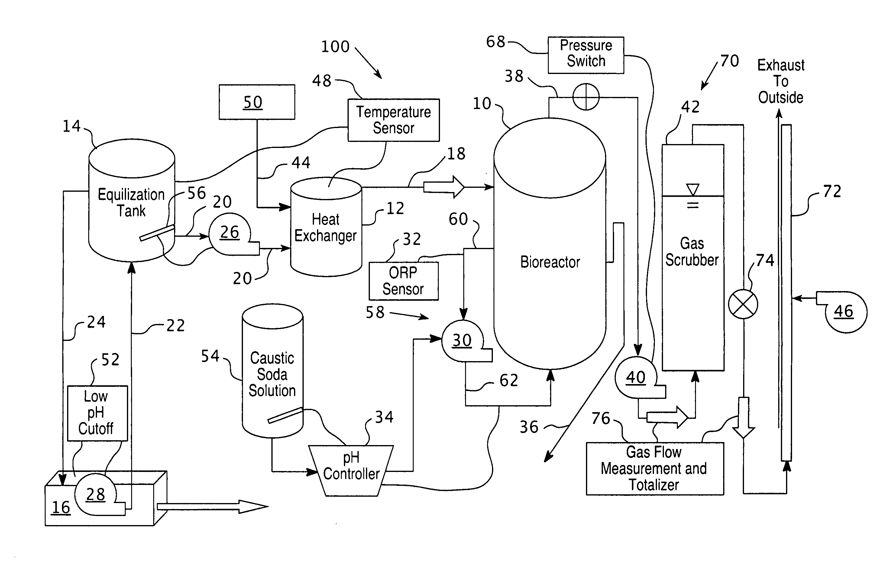
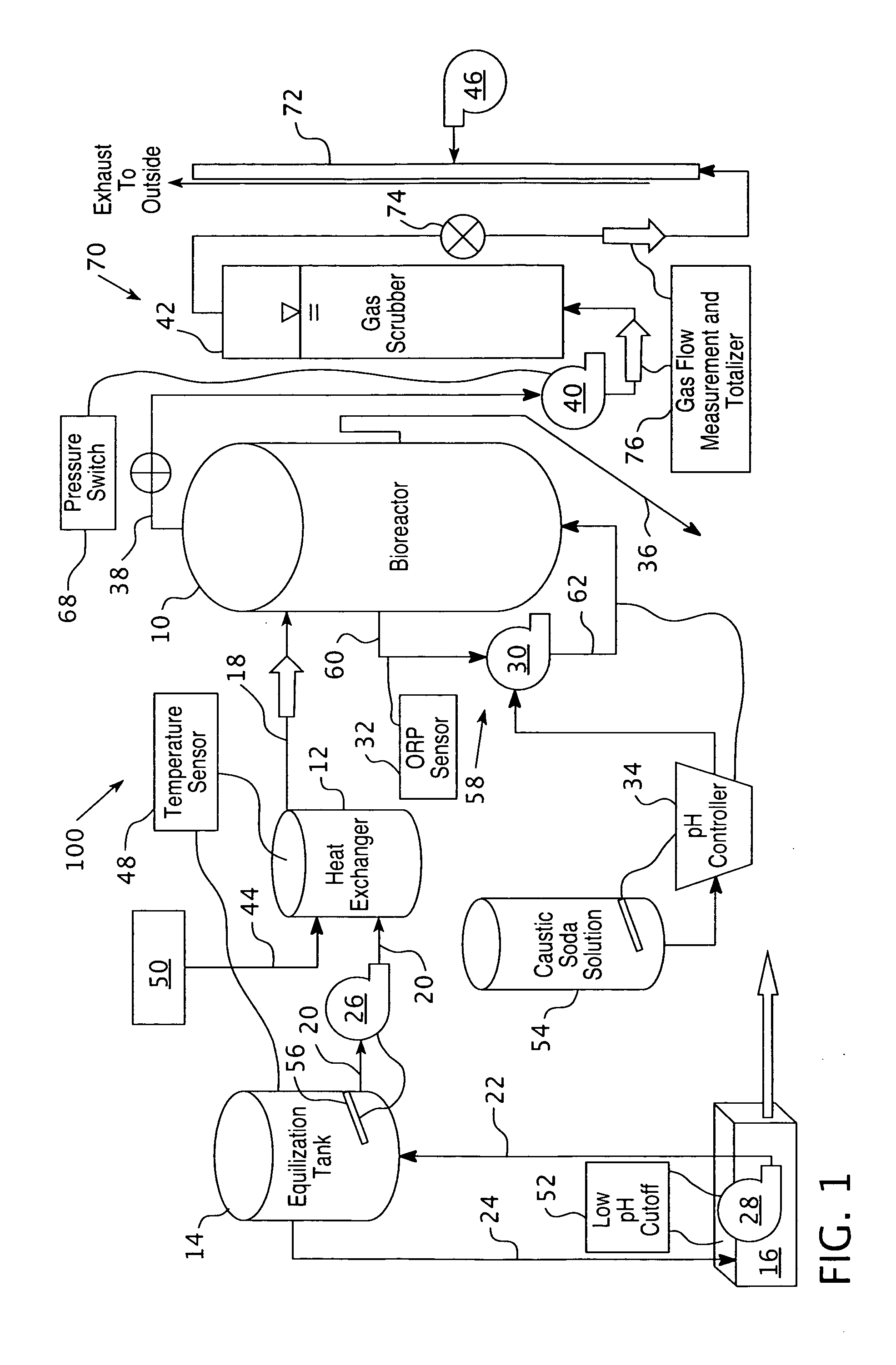
[0079] The apparatus combines a bioreactor with a grape juice facility. The organic feed material is a grape juice waste product diluted in tap water at approximately 32 mL of juice per liter. The solution uses chlorine-free tap water or is aerated previously for 24 hours to substantially remove chlorine. The dilution and aeration occur in a treatment container. The organic feed material is then conveyed into the feed container through a passage.

[0080] The organic feed material is heated in the feed container to about 65° C. for about 10 minutes to substantially deactivate methanogens. The organic feed material is heated with a heat exchanger with excess heat from the grape juice facility. The organic feed material is conveyed through a passage to the bioreactor wherein it is further inoculated with Kleibsiella oxytoca. The resultant biogases produced by the microorganisms metabolizing the organic feed material include hydrogen without any substantial methane.

example 2

[0081] A multiplicity of reactors were initially operated at pH 4.0 and a flow rate of 2.5 mL min−1, resulting in a hydraulic retention time (HRT) of about 13 h (0.55 d). This is equivalent to a dilution rate of 1.8 d−1. After one week all six reactors were at pH 4.0, the ORP ranged from −300 to −450 mV, total gas production averaged 1.6 L d−1 and hydrogen production averaged 0.8 L d−1. The mean COD of the organic feed material during this period was 4,000 mg L−1 and the mean effluent COD was 2,800 mg L−1, for a reduction of 30%. After one week, the pHs of certain reactors were increased by one half unit per day until the six reactors were established at different pH levels ranging from 4.0 to 6.5. Over the next three weeks at the new pH settings, samples were collected and analyzed each weekday. It was found that the optimum for gas production in this embodiment was pH 5.0 at 1.48 L hydrogen d−1 (Table 2). This was equivalent to about 0.75 volumetric units of hydrogen per unit of r...


PUM


Abstract

The present invention provides a hydrogen production apparatus, where a bioreactor is combined with an industrial facility such that the industrial facility heats an organic feed material prior to conveyance of the organic feed material into the bioreactor. The apparatus includes a bioreactor, a feed container, a heating means such as a heat exchanger and an industrial facility with a heat waste source.

Description

CROSS REFERENCE TO RELATED APPLICATION [0001] This application claims priority under 35 U.S.C. §119(e) to U.S. Provisional Patent Application Ser. No. 60 / 686,008, filed May 31, 2005, entitled “HYDROGEN PRODUCING APPARATUS UTILIZING EXCESS HEAT FROM A INDUSTRIAL FACILITY”FIELD OF THE INVENTION [0002] The present invention relates generally to an apparatus for concentrated production of hydrogen from hydrogen producing microorganism cultures. More particularly, the invention relates to an apparatus that synergistically combines a hydrogen production system with an industrial facility, wherein the industrial facility may be unrelated to the production of hydrogen apart from the claimed apparatus. The hydrogen production system uses heat or heat waste that is produced during typical usage of the industrial facility, thereby reducing energy costs of the hydrogen production system and conserving energy from the facility. The industrial facility may also produce organic waste products that...

Claims


Application Information

Patent Timeline
IPC IPC(8): C12M3/00
CPCC12M21/04C12M41/26C12M41/28C12M45/20C12M47/18Y02E50/30
Inventor FELDER, MITCHELLFELDER, JUSTINDIZ, HARRY
Owner FELDER MITCHELL
Why Eureka
Try Eureka