Cooling system used for hybrid-powered automobile

a technology of hybrid power and cooling system, which is applied in the direction of indirect heat exchangers, machines/engines, light and heating apparatus, etc., can solve the problems of insufficient quantity of heat to be radiated from the radiator for engine use, the inability of the condenser and the inability of the radiator for electric parts to exhibit a necessary cooling performance. to achieve the effect of enhancing the performance of the radiator and enhancing the property of the radiator

Inactive Publication Date: 2006-12-14
SANADA RYOUICHI +2
View PDF19 Cites 16 Cited by
  • Summary
  • Abstract
  • Description
  • Claims
  • Application Information

AI Technical Summary

Benefits of technology

[0012] In view of the above points, it is an object of the present invention to enhance the performance of a radiator for electric parts use and a condenser in a cooling system used for a hybrid-powered automobile having three heat exchangers. It is also an object of the present invention to enhance the property of mounting the radiator for electric parts use and the condenser on a vehicle.

Problems solved by technology

Therefore, problems are caused when the three row mounting type cooling system is mounted on the vehicle.
Therefore, it becomes impossible for the condenser to exhibit a necessary cooling performance.
Therefore, it becomes impossible for the radiator for electric parts use to exhibit a necessary cooling performance.
A quantity of heat to be radiated from the radiator for engine use becomes insufficient.

Method used


Image

  • Cooling system used for hybrid-powered automobile
  • Cooling system used for hybrid-powered automobile
  • Cooling system used for hybrid-powered automobile

Examples


first embodiment

[0076] The structure of the condenser 12 of this embodiment is different from that of the As shown in FIG. 4, the condenser 12 of this embodiment is a so-called sub-cool condenser. The condenser 12 includes: a condenser portion 127 for exchanging heat between the gas-phase refrigerant, which has been discharged from the compressor 11, and the outside air so as to condense the refrigerant; a modulator 128 for separating the refrigerant, which has flowed out from the condenser portion 127, into the gas-phase refrigerant and the liquid-phase refrigerant; and a sub-cooler portion 129 for cooling the liquid-phase refrigerant which has flowed out from the modulator 128.

[0077] Both the condenser portion 127 and the sub-cooler portion 129 are of the cross-flow type. The sub-cooler portion 129 is arranged below the condenser portion 127, and the modulator 128 is arranged on the sides of the condenser portion 127 and the sub-cooler portion 129. An upper portion of the modulator 128 protrudes...

third embodiment

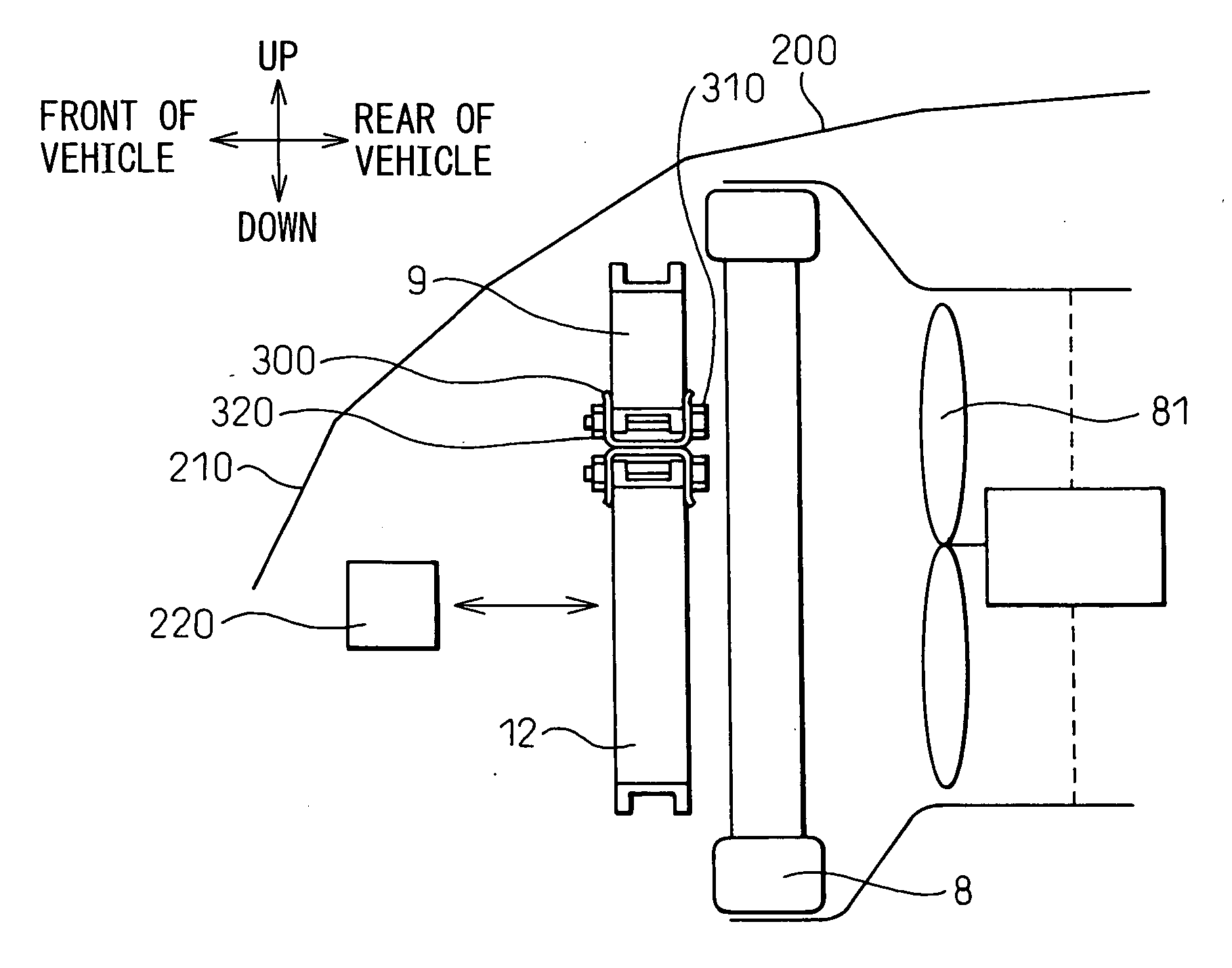
[0087] In this embodiment, the radiator 9 for electric parts use and the condenser 12 are arranged differently from those of the As shown in FIG. 7, the condenser 12 may be arranged on an upper side of the radiator 9 for electric parts use.

[0088] The sixth and the seventh embodiment of the present invention will be explained below. FIG. 8 is a front view in which the cooling system of the sixth embodiment is viewed from the front of a vehicle, and FIG. 9 is a front view in which the cooling system of the seventh embodiment is viewed from the front of a vehicle. In this connection, similar reference characters are used to indicate similar parts in the fourth embodiment (shown in FIG. 6) and the sixth and the seventh embodiment, and the explanations are omitted here.

[0089] In the third embodiment, the radiator 9 for electric parts use and the condenser 12 are of the cross-flow type. However, only the condenser 12 may be changed into the down-flow type as in the sixth embodiment show...

second embodiment

[0093] In this embodiment, the radiator 9 for electric parts use and the condenser 12 are arranged differently from the As shown in FIG. 11, in the case where the condenser 12 is a so-called sub-cool condenser, the radiator 9 for electric parts use and the condenser 12 may be arranged in the traverse direction of the vehicle.

[0094] The tenth embodiment of the present invention will be explained below. FIG. 12 is a view showing a cooling water tube in a cooling system according to the tenth embodiment, and FIG. 13 is a view showing a refrigerant tube in a cooling system according to the tenth embodiment.

[0095] As a cooling water tube 91 in the radiator 9 for electric parts use in each of the above embodiments, a flattened tube may be used, which is made by bending an aluminum sheet to be tubular and having a flattened cross section, as shown in FIG. 12. This cooling tube 91 comprises one cooling water passage 91a in which a cooling water flows.

[0096] Also, as a refrigerant tubes 1...


PUM


Abstract

A radiator 9 for electric parts use, which cools an inverter and others relating to the control of an electric motor, and a condenser 12 for condensing refrigerant are arranged in parallel with each other with respect to the direction of an air flow on an upstream side of the air flow of a radiator 8 for engine use. Due to the above arrangement, as the air temperatures at the inlets of the radiator 8 for electric parts use and the condenser 12 are low, a temperature difference between air and cooling water and a temperature difference between air and refrigerant are increased, and it becomes possible to enhance the performance of the radiator 8 for electric parts use and the condenser 12.

Description

BACKGROUND OF THE INVENTION [0001] 1. Field of the Invention [0002] The present invention relates to a cooling system used for a hybrid-powered automobile which is driven by a combination of a water-cooled engine and an electric motor. [0003] 2. Description of the Related Art [0004] The cooling system used for a hybrid-powered automobile includes: a radiator for engine use which cools an engine; and a radiator for electric parts use which cools electric parts such as an inverter and also cools an electric motor. In some cases, the cooling system used for a hybrid-powered automobile further includes a condenser which cools the gas-phase refrigerant, at a high temperature, flowing in an air-conditioner. [0005] In the case where the above three heat exchangers are provided in the cooling system used for a hybrid-powered automobile, the radiator for cooling electric parts, the condenser for cooling the gas-phase refrigerant and the radiator for cooling the engine are arranged in series ...

Claims


Application Information

Patent Timeline
Patent Type & Authority Applications(United States)
IPC IPC(8): B60H1/00B60H1/22B60H1/32B60K6/22B60K6/40B60K6/44B60K6/54B60K11/04B60L15/00F01P3/18F25B27/00F25B39/04F28D1/04F28F9/00
CPCF01P2003/182F01P2003/185F01P2050/24F28F9/002F01P2060/14F25B39/04F28D1/0452F01P2050/30
Inventor SANADA, RYOUICHIHAYASAKA, ATSUSHISUGIMOTO, NAOKI
Owner SANADA RYOUICHI
Why Eureka
Try Eureka