Image processing apparatus and method, computer program, and storage medium

Inactive Publication Date: 2006-12-14
CANON KK
View PDF15 Cites 31 Cited by
  • Summary
  • Abstract
  • Description
  • Claims
  • Application Information

AI Technical Summary

Benefits of technology

[0026] According to the present invention, an image region exhibiting poor color tone of an eye image can be detected with high precision in a device environment in which the memory resources that can be assigned to the detection are limited. Th

Problems solved by technology

In general, as the light source position of the photographic flash is closer to the optical axis of the lens, the red-eye effect occurs more readily, and a measure against this phenomenon is a critical issue.
However, this method consumes a battery more than normal photographing, and changes the expression of the object due to the pre-light emission.
For this reason, the user must display the vicinity of a region to be corrected of image data in an enlarged scale, and must then designate the correction region, thus requiring troublesome operations.
However, on a device such as a digital camera, printer, or the like, which comprises only a display device of several inches, operations for enlarging an image, and designating the correction re

Method used


Image

  • Image processing apparatus and method, computer program, and storage medium
  • Image processing apparatus and method, computer program, and storage medium
  • Image processing apparatus and method, computer program, and storage medium

Examples


Example

First Embodiment

[Arrangement of Apparatus]

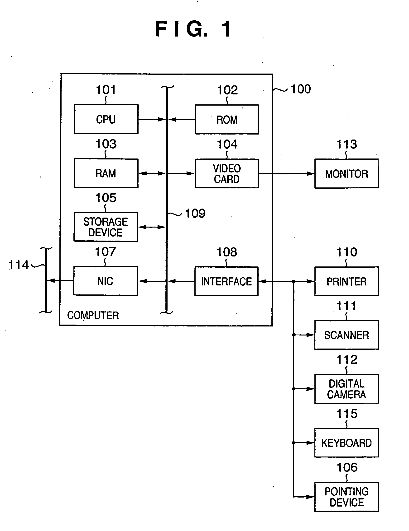
[0069]FIG. 1 is a block diagram showing the arrangement of a computer (image processing apparatus) which executes image processing of the first embodiment.

[0070] A computer 100 comprises a CPU 101, a ROM 102, a RAM 103, a video card 104 which connects a monitor 113 (which may comprise a touch panel), and a storage device 105 such as a hard disk drive, memory card, and the like. Also, the computer 100 comprises an interface 108 for a serial bus such as USB, IEEE1394, or the like, which connects a pointing device 106 such as a mouse, stylus, tablet, or the like, a keyboard 107, and the like. Furthermore, the computer 100 comprises a network interface card (NIC) 107 which connects a network 114. These components are interconnected via a system bus 109. A printer 110, scanner 111, digital camera 112, and the like can be connected to the interface 108.

[0071] The CPU 101 loads programs (including a program of image processing to be described b...

Example

Second Embodiment

[0199] Image processing according to the second embodiment of the present invention will be described below. Note that the same reference numerals in the second embodiment denote the same parts as in the first embodiment, and a detailed description thereof will be omitted.

[0200] The adaptive binarization processing described in the first embodiment sets the window 403 (see FIG. 4) having a predetermined size in the left direction (front side of the main scan direction) of the interest pixel. The average value Er(ave) of the evaluation values of pixels in the window 403 is calculated, and whether or not the interest pixel forms a red color region is checked using the average value Er(ave) as a threshold, thus attaining binarization. Such method refers to a small number of pixels to calculate the threshold, and can speed up the processing. However, since the window 403 is set in only the left direction of the interest pixel, the binarization result depends on the pr...

Example

Third Embodiment

[0210] Image processing according to the third embodiment of the present invention will be described hereinafter. Note that the same reference numerals in the third embodiment denote the same parts as in the first and second embodiments, and a detailed description thereof will be omitted.

[0211] In the first and second embodiments, the method for extracting pixels which form a red color region by executing the adaptive binarization processing that focuses attention on the evaluation value Er given by equation (3) has been described. Such method often detects pixels of an inner or outer canthus portion 2202 as pixels which form a red color region in addition to a pupil portion 2201 of a red-eye image. When the inner or outer canthus portion 2202 is enlarged, many “dark red” pixels specified by, e.g., (R, G, B)=(81, 41, 31) exist. The evaluation value of this pixel is 49%, i.e., a relatively large value. For this reason, in the adaptive binarization processing of the ...


PUM


Abstract

An embedded system of a digital camera or printer has limited available memory resources. Under such environment, devices are required to detect a red-eye region from a high-resolution image. To solve this problem, an input image is divided into band images each including a predetermined number of lines, so that an overlap area exists between neighboring band images, and candidate pixels which form an image region exhibiting poor color tone are extracted for each band image. The band image which is to undergo characteristic amount determination is decided based on the position of the candidate region which includes the candidate pixels in the overlap area.

Description

FIELD OF THE INVENTION [0001] The present invention relates to an image processing apparatus and method and, more particularly, to image processing for detecting an image region exhibiting poor color tone of an eye image. BACKGROUND OF THE INVENTION [0002] A method of correcting poor color tone of an eye image due to a photographic flash of a camera has been proposed. Note that poor color tone of an eye image is generally well known as a red-eye effect. The red-eye effect is as follows. That is, when a person or an animal such as a dog, cat, or the like is photographed using a photographic flash under an insufficient illumination environment, the flash light that has entered the opening pupil part is reflected by the eyeground, and capillaries gleam red. Since a person who has a pale pigment color (or a light pigment) has a higher transmittance of the pupil, i.e., crystal lens, the red-eye effect tends to occur more frequently with such person. [0003] In recent years, digital camera...

Claims


Application Information

Patent Timeline
IPC IPC(8): G06K9/00
CPCG06K9/0061G06T7/0081G06T7/408G06T2207/10024G06T2207/30201G06T2207/30216G06T5/005G06T2207/20021G06T7/11G06T7/90G06V40/193
Inventor UMEDA, KIYOSHI
Owner CANON KK
Why Eureka
Try Eureka