Optical fiber drawing apparatus, sealing mechanism for the same, and method for drawing an optical fiber

a sealing mechanism and optical fiber technology, applied in the direction of instruments, washing machines, furnaces, etc., can solve the problems of increased fluctuation in the outer diameter of the optical fiber, loss of sealing properties, and use of carbon fiber, and achieve the effect of simple structur

Inactive Publication Date: 2006-12-14
HITACHI CABLE
View PDF1 Cites 46 Cited by
  • Summary
  • Abstract
  • Description
  • Claims
  • Application Information

AI Technical Summary

Benefits of technology

[0046] According to the invention, it is possible to provide the optical fiber drawing apparatus, the sealing mechanism for the same, and the method for drawing an optic

Problems solved by technology

Since there is also a limit in shrinkage of the ring thereafter, the sealing property will be lost.
Further, from the viewpoint of dusting and consumption, there are a lot of disadvantages in the use of the carbon felt.
As a result, the fluctuation in the outer diameter of the optical fiber is increased, the strength of the optical fiber is decreased, the optical characteristics of the optical fiber are d

Method used


Image

  • Optical fiber drawing apparatus, sealing mechanism for the same, and method for drawing an optical fiber
  • Optical fiber drawing apparatus, sealing mechanism for the same, and method for drawing an optical fiber
  • Optical fiber drawing apparatus, sealing mechanism for the same, and method for drawing an optical fiber

Examples


embodiment

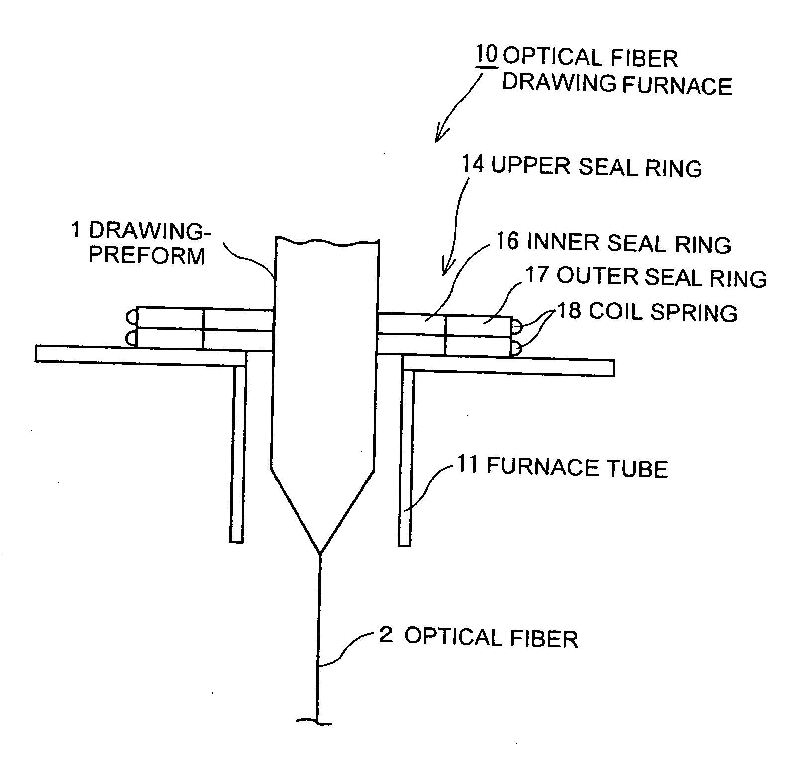
[0078] The upper seal ring 14 is manufactured as follows. The inner seal ring 16 attached to the drawing-preform 1 is made of graphite in consideration of the prevention of external damages to the glass-preform and the heat resistance. The outer seal ring 17 is made of ceramics in consideration of the heat shield to the coil spring 18 provided at the outer periphery of the outer seal ring 17.

[0079] When the ring shape is formed by connecting the inner seal ring pieces 16A, a curvature of a part closely contacting with the drawing-preform 1 is determined to provide a radius that can constitute the inner diameter smaller by about 2 mm than the minimum diameter of the drawing-preform 1. The curvature of an inner periphery part of the outer seal ring piece 17A is conformed to the curvature of an outer periphery part of the inner seal ring piece 16A.

[0080] 12 pieces of the inner seal ring pieces 16A and the outer seal ring pieces 17A were prepared, respectively, the inner seal ring 16 ...


PUM

PropertyMeasurementUnit
Currentaaaaaaaaaa
Lengthaaaaaaaaaa
Diameteraaaaaaaaaa

Abstract

An inner seal ring 16 is composed by connecting a plurality of inner seal ring pieces 16A, an outer seal ring 17 is composed by connecting a plurality of outer seal ring pieces 17A provided at an outer periphery of the inner seal ring 16, and a coil spring 18 is arranged at an outer periphery of the outer seal ring 17. The inner seal ring 16 and the outer seal ring 17 are piled for two or more stages, respectively. A connecting part of the inner seal ring pieces 16A and a connecting part of the outer seal ring pieces 17 are arranged not to overlap each other. An inner diameter of the inner seal ring 16 is variable in accordance with an outer diameter in vertical direction of a drawing-preform 1 by using a coil spring 18.

Description

[0001] The present application is based on Japanese Patent Application No. 2005-170419 filed on Jun. 10, 2005, the entire contents of which are incorporated herein by reference. BACKGROUND OF THE INVENTION [0002] 1. Field of the Invention [0003] This invention relates to an optical fiber drawing apparatus, a sealing mechanism for the same, and a method for drawing an optical fiber, and more particularly, to an optical fiber drawing apparatus, a sealing mechanism for the same, and a method for drawing an optical fiber which has simple structure and can maintain the sealing property in a furnace tube even if variation in the outer diameter of the preform is large. [0004] 2. Description of the Related Art [0005]FIG. 1 is a schematic illustration showing a conventional optical fiber drawing apparatus (drawing furnace). [0006] An optical fiber drawing furnace 20 mainly comprises a furnace tube 21 to which an optical fiber drawing-preform 1 is inserted, a heater 22 for heating the inserte...

Claims


Application Information

Patent Timeline
IPC IPC(8): F16B43/02C03B37/085C03B37/025
CPCC03B37/029C03B2205/82C03B2205/80Y02P40/57
Inventor SHIONO, MITSUHIRO
Owner HITACHI CABLE
Why Eureka
Try Eureka