
Computing with biomolecules

a biomolecule and computing technology, applied in the field of molecular computing units, can solve the problems of slow computation speed, large complexity of biological components, and limited half-lives of most biological components, and achieve the effects of improving the efficiency of biological components

Inactive Publication Date: 2006-12-14
UNIV OF MARYLAND +1
View PDF4 Cites 17 Cited by
  • Summary
  • Abstract
  • Description
  • Claims
  • Application Information

AI Technical Summary

Benefits of technology

[0043] Unless otherwise defined, all technical and scientific terms used herein have the same meaning as commonly understood by one of ordinary skill in the art to which this invention belongs. Although methods and materials similar or equivalent to those described herein can be used in the practice or testing of the present invention, suitable methods and materials are described below. In case of conflict, the patent specification, including definitions, will control. In addition, the materials, methods, and examples are illustrative only and not intended to be limiting.

Problems solved by technology

However, biological systems have significant disadvantages compared to silicon-based systems including slower speed of computation (GHZ for silicon-based computers compared with microseconds to milliseconds for biological reactions), durability (most biological components have limited half-lives), and reliability (most biological reactions are prone to a non-negligible error rates).
Nevertheless, these methods require the use of an exponential number (in the size of the problem) of molecules since their mode of operation is based on “a massive parallel attack”.
While this exponential dependency may be unavoidable in dealing with NP-hard problems, it will lead to a very inefficient solution to more tractable problems, where a more direct and efficient approach might be more appropriate.
In addition, these systems require specific encoding and implementation for each problem, and thus, in a practical sense, they do not offer a way of utilizing such procedures as a generic way to solve general computational problems.
While the model and its biological implementation are elegant, Turing machines are not efficient computational devices, and “programs” written for Turing machines are long and cumbersome.
While this switch design is very elegant, it is not clear how such elements can be hooked together to form a computing network.

Method used


Image

  • Computing with biomolecules
  • Computing with biomolecules
  • Computing with biomolecules

Examples


example 1

The Molecular Computing Unit: Choice of Gates for the Computation Scheme

[0126] The following example schematically describes in abstract terms, the design of a bio-molecular system that is capable of carrying out a computation that follows the logic of a Boolean circuit based on NAND gates.

[0127] The choice of universal Boolean gates—Boolean algebra deals with calculating truth values (TRUE or FALSE) of logical statements and is the underlying mathematical tool of any digital circuit. Every Boolean function can be expressed using the two gates of AND and NOT (or OR and NOT). However, to keep the design simple and uniform, a single universal gate that can be combined to express any function was chosen. The NAND gate is one such gate (NOR is another possible gate). The NAND gate is an AND gate with the output INVERTED. The AND gate outputs “1” when ALL of the inputs are “1”, otherwise the output is “0”. The INVERTED gate (or the NOT gate) performs the inversion of the input. When th...

example 2

The Biological Implementation of the Molecular Computing Unit

[0139] The following example describes a detailed account of how the biological reactions chosen can be used to implement the scheme. The following reactions are certainly not the only possibilities for implementing a general design of a computational network, and some possible alternative mechanisms are also suggested. Regardless of the actual reactions that are ultimately used in engineering a practical implementation, the model proposed here is a general one, in the sense that the same design can be used to perform any logical calculation via biological computation.

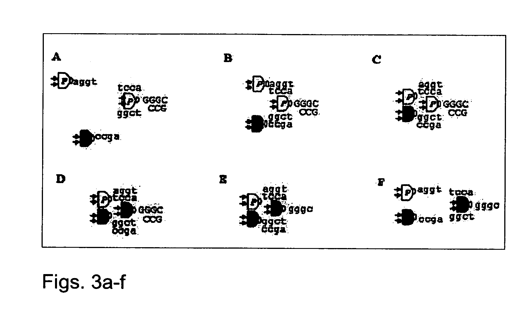
[0140] The model proposed above is based on general ideas but must be implemented using specific biological processes and reactions. In this section, one set of reactions is suggested that could carry out the tasks required. The feasibility of these reactions is further described hereinbelow.

[0141] Formation of “wires” is based on recognition between DNA s...

example 3

The Majority Circuit

[0148] The following example provides a simple biological implementation of a circuit that calculates the majority function of its three inputs.

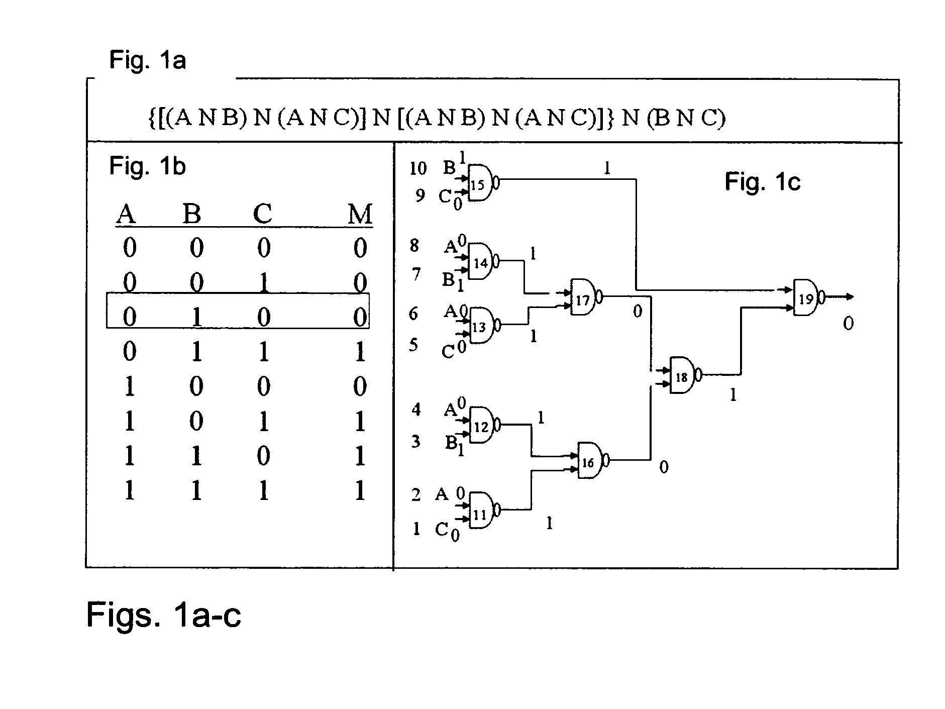
[0149]FIG. 1b provides the Truth Table and the logical design for this circuit. The output is “1” if at least two of its three inputs are “1”, otherwise it is “0”. While this is a very simple calculation that can be performed by many analog processes, the same approach can be used to implement any logical circuit, regardless of its complexity.

[0150] The circuit presented in FIGS. 1a-c has 19 elements. Elements 1 to 10 are inputs consisting of molecules similar to the rest of the computational elements, the only difference being that they have preset phosphorylation states, reflecting the required logical values. Gate 19 is the output gate. Thus, the system consists of 19 elements, each with the same protein component, capable of performing the phosphorylation and the exonuclease reactions, but each carrying different D...


PUM

PropertyMeasurementUnit
volumeaaaaaaaaaa
catalytic functionsaaaaaaaaaa
nucleic acid sequenceaaaaaaaaaa

Abstract

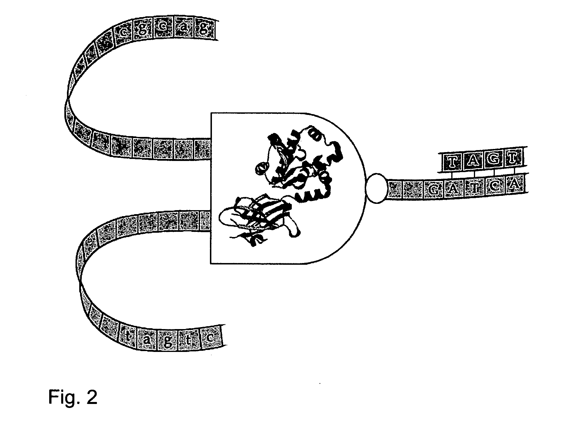
The present invention is of a molecular entity comprising a polypeptide core and nucleic acid sequences attached thereto which is capable of forming a universal logic gate such as the NAND gate. Specifically, the present invention can be used to device a molecular computing unit which can be used to detect biological markers and administer therapeutic moieties.

Description

RELATED APPLICATION [0001] This application claims the benefit of U.S. Provisional Patent Application No. 60 / 688,329, filed on Jun. 8, 2005, the content of which is hereby incorporated by reference.FIELD AND BACKGROUND OF THE INVENTION [0002] The present invention relates to a molecular computing unit and, more particularly, to methods of generating and using same in various biological implications. [0003] In recent years there has been significant interest in exploring the possibilities of biological computation. A large number of studies have investigated various ideas for using biological molecules to carry out various types of calculations and computations (1-6). [0004] Biological systems perform computations in living organisms on multiple levels, from the cognitive to the molecular. Examples range from the brain's ability to perform numerical calculations or analyze images to the immune system's ability to identify intruders. Other cellular activities, such as maintaining home...

Claims


Application Information

Patent Timeline
Patent Type & Authority Applications(United States)
IPC IPC(8): H01L29/08C12Q1/68C12M1/34H01L35/24H01L51/00H10N10/856
CPCB82Y10/00G06N99/007G11C13/0014G06N3/002H01L51/0093H01L51/0595G11C13/0019H10K85/761H10K10/701
Inventor UNGER, RONMOULT, JOHN
Owner UNIV OF MARYLAND
Learn More