Phased array ultrasonic testing system and methods of examination and modeling employing the same

a phased array and testing system technology, applied in the direction of vibration measurement in solids, instruments, specific gravity measurement, etc., can solve the problems of complex curves, ultrasonic testing inspection becomes more and more difficult, and failure of components,

Active Publication Date: 2006-12-21
SIEMENS ENERGY INC
View PDF20 Cites 50 Cited by
  • Summary
  • Abstract
  • Description
  • Claims
  • Application Information

AI Technical Summary

Benefits of technology

[0023] The method may further comprise programming a controller of the control system using a computer, including defining the focal laws for the ultrasonic beam. The programming step may comprise defining as the focal laws, focal laws selected from the group consisting of beam angle, focal distance, beam width, and focal point.

Problems solved by technology

SCC can result from the combination of high operational forces and prolonged exposure to a corrosive environment.
Defects in these and other areas must be identified before they progress to a point where they could result in component failure.
Inspection using ultrasonic testing techniques gets more and more difficult as the complexity of the geometry of the object to be tested increases.
For instance, compound curves make ultrasonic testing very difficult because one portion of the compound curve may, for example, be convex and therefore function to diverge the ultrasonic wave being projected by the transducer while another portion may, for example, be concave and therefore tend to converge the beam.
As a result of the complexity of the design, commercially available ultrasonic inspection has been limited.
NDE has, therefore, been largely limited to surface sensitive techniques such as magnetic particle, dye penetrant, or eddy current.
Accordingly, it is appreciated that examining Siemens Westinghouse discs and blade attachments is more difficult than examining discs and blade attachments of other manufacturers.
However, the method is limited in application to the relatively simple geometry of the straddle-mount design, as previously discussed.
The disclosed probe mounting location and scanning methods would not sufficiently accommodate the complex geometry of, for example, the axial blade attachment design to provide accurate and reliable inspection results.
However, the method is generally limited to linear or one-dimensional inspection probes and methods, and to the requirement that the probes be placed on the disc at a location across from the keyway area.

Method used


Image

  • Phased array ultrasonic testing system and methods of examination and modeling employing the same
  • Phased array ultrasonic testing system and methods of examination and modeling employing the same
  • Phased array ultrasonic testing system and methods of examination and modeling employing the same

Examples


example

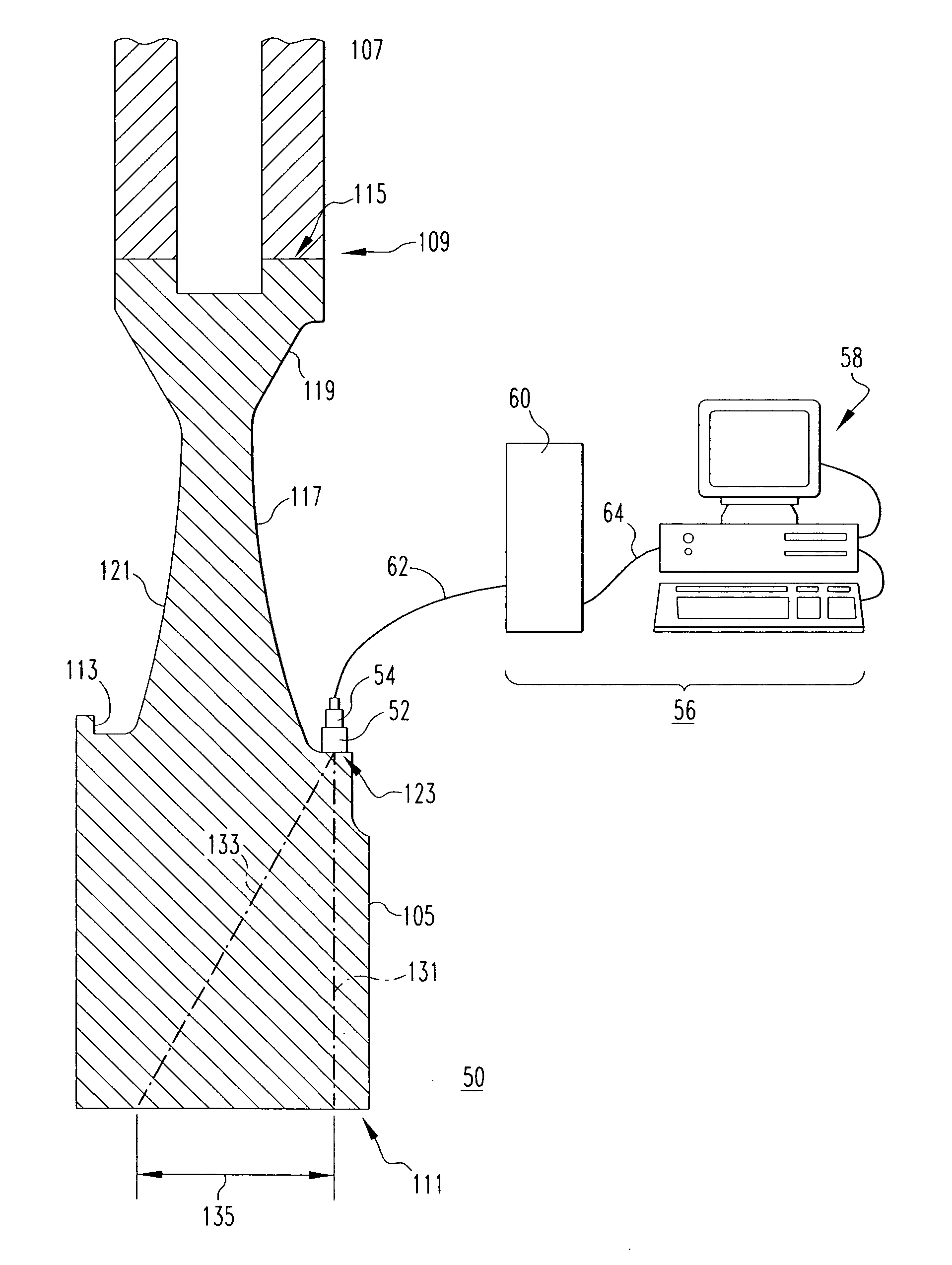
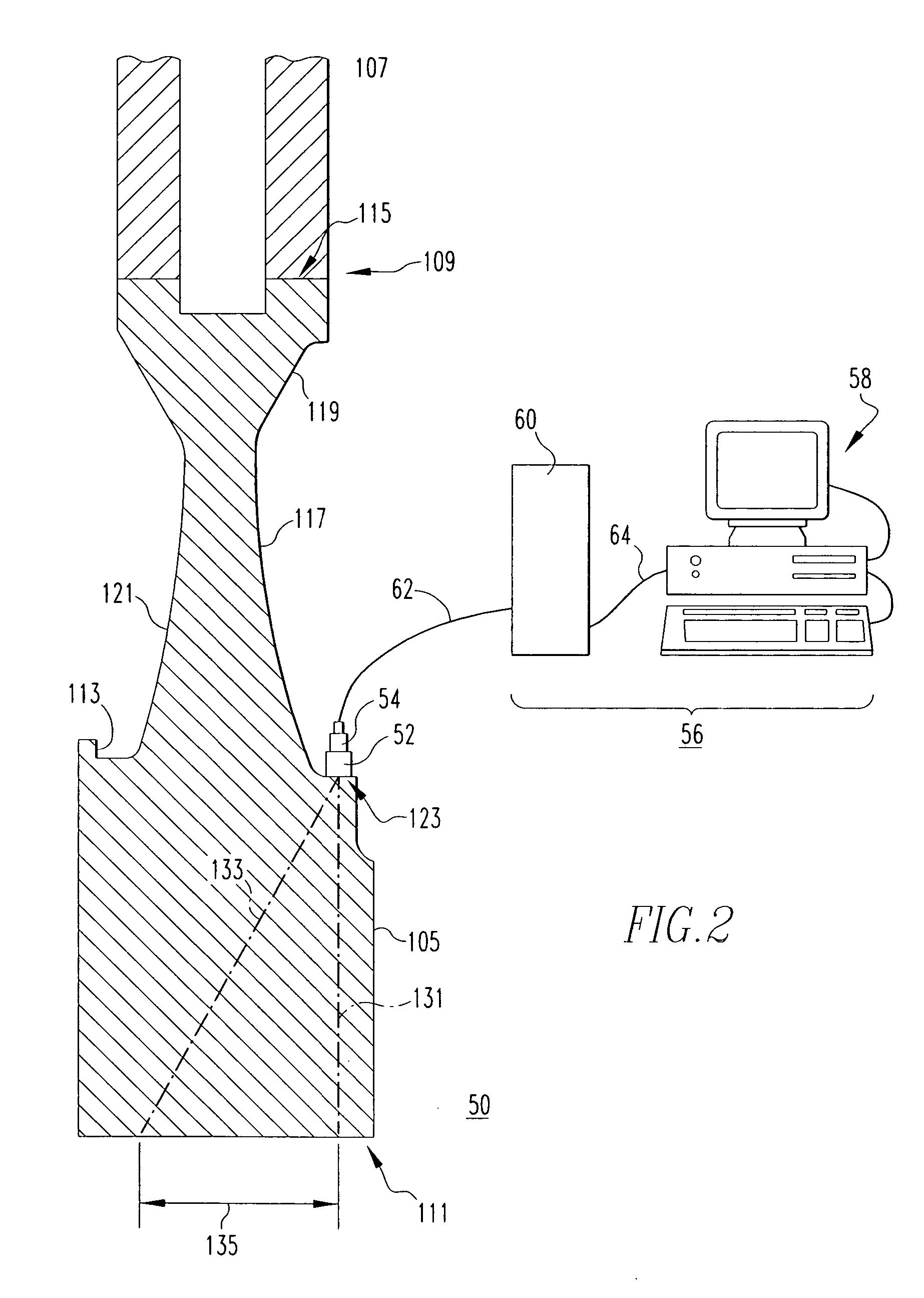
[0045] For this example, the area of the disc bore 111 to be examined is designated by the dimension 135, which is about 2 inches (5.08 centimeters) wide. In order to inspect area 135 using known ultrasonic testing techniques would require about six different wedges (not shown), whereas the same area 135 can be inspected using a single wedge 52 in accordance with the exemplary phased array ultrasonic testing system 50. This is, in large part, due to the fact that known 1D techniques are limited in their ability to steer the beam 131 over a relatively large area. Specifically, as previously discussed, one-dimensional probes can only steer in one direction which makes it difficult to control the beam as desired when the wedge and probe are mounted on a surface that is not flat. The various probe mounting surfaces on disc 105 (two different mounting surfaces are shown in FIGS. 2 and 3, respectively), are not flat. Therefore, the aforementioned plurality (e.g., six) of different wedges ...


PUM

PropertyMeasurementUnit
timeaaaaaaaaaa
array ultrasonic testingaaaaaaaaaa
phased array ultrasonic testingaaaaaaaaaa

Abstract

A phased array ultrasonic testing system is for examining turbine disc bores and blade attachments for discontinuities, such as stress corrosion cracking. The system is particularly suited to perform an accurate and efficient inspection of components despite their having a relatively complex geometry, such as axial entry blade attachments and bores of associated discs. The system includes a control system with a computer and a controller for programming, emitting, and steering an ultrasonic beam via at least one two-dimensional phased array probe, thereby precisely inspecting the area of interest while simultaneously accommodating the aforementioned complex geometry of the disc or blade attachment. Computer control of the beam permits the number of inspection locations and the number of different probe wedges to be reduced providing for an efficient, timely inspection. Methods of profiling and examining turbine components of known and unknown geometries, are also disclosed.

Description

BACKGROUND OF THE INVENTION [0001] 1. Field of the Invention [0002] The present invention relates generally to ultrasonic nondestructive testing and, more particularly, to a phased array ultrasonic testing system for inspecting turbine blade attachments and disc bores. The invention also relates to methods of examining turbine blades and disc bores, and modeling turbine components of unknown geometry using a phased array ultrasonic testing system. [0003] 2. Background Information [0004] Gas and steam turbines for electrical power generation must be routinely inspected in order to detect discontinuities, such as stress corrosion cracking (SCC). SCC can result from the combination of high operational forces and prolonged exposure to a corrosive environment. Two portions of the turbine which are areas of relative stress concentration and, therefore, are especially susceptible to SCC, are the blade attachments, where the base or root of the turbine blades attach to the turbine disc, and...

Claims


Application Information

Patent Timeline
Patent Type & Authority Applications(United States)
IPC IPC(8): G01N29/00
CPCG01N29/262G01N2291/044G01N2291/106G01N2291/2693G10K11/34
Inventor FAIR, MICHAELABBASI, WAHEED A.METALA, MICHAEL J.MATULEWICZ, WALTER
Owner SIEMENS ENERGY INC
Why Eureka
Try Eureka