Insulation package arrangement for insulating the interior of an aircraft fuselage

Inactive Publication Date: 2006-12-21
AIRBUS OPERATIONS GMBH
View PDF23 Cites 44 Cited by
  • Summary
  • Abstract
  • Description
  • Claims
  • Application Information

AI Technical Summary

Benefits of technology

[0012] It is believed that an improved insulation package arrangement for an aircraft may be provided, which arrangement may be used for interior insulation, to such an extent that with it the flames of a seat of fire acting from outside the aircraft environment are essentially prevented from entering the cabin space of an aircraft (that has made an emergency landing) or a fire withstanding time may be extended. The design of the insulation package and its attachment to the fuselage structure is believed to be suitable for implementing an increase in the fire protection safety of separated interior regions that are situated near a structural outer skin.
[00

Problems solved by technology

Furthermore, conventional insulation attachment elements are made from non-metal materials (plastics), which in the case of a fire may melt.
Thus, there is always a desire to extend a period of time the attachment

Method used


Image

  • Insulation package arrangement for insulating the interior of an aircraft fuselage
  • Insulation package arrangement for insulating the interior of an aircraft fuselage
  • Insulation package arrangement for insulating the interior of an aircraft fuselage

Examples


Embodiment Construction

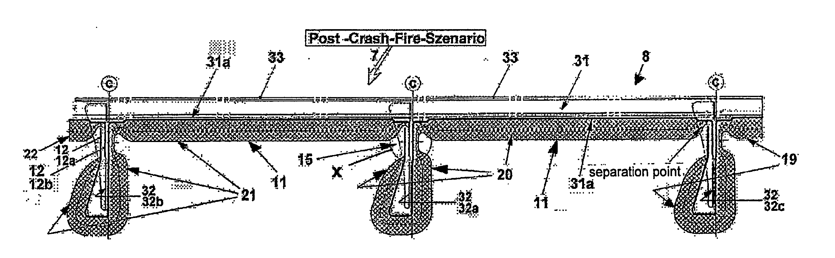
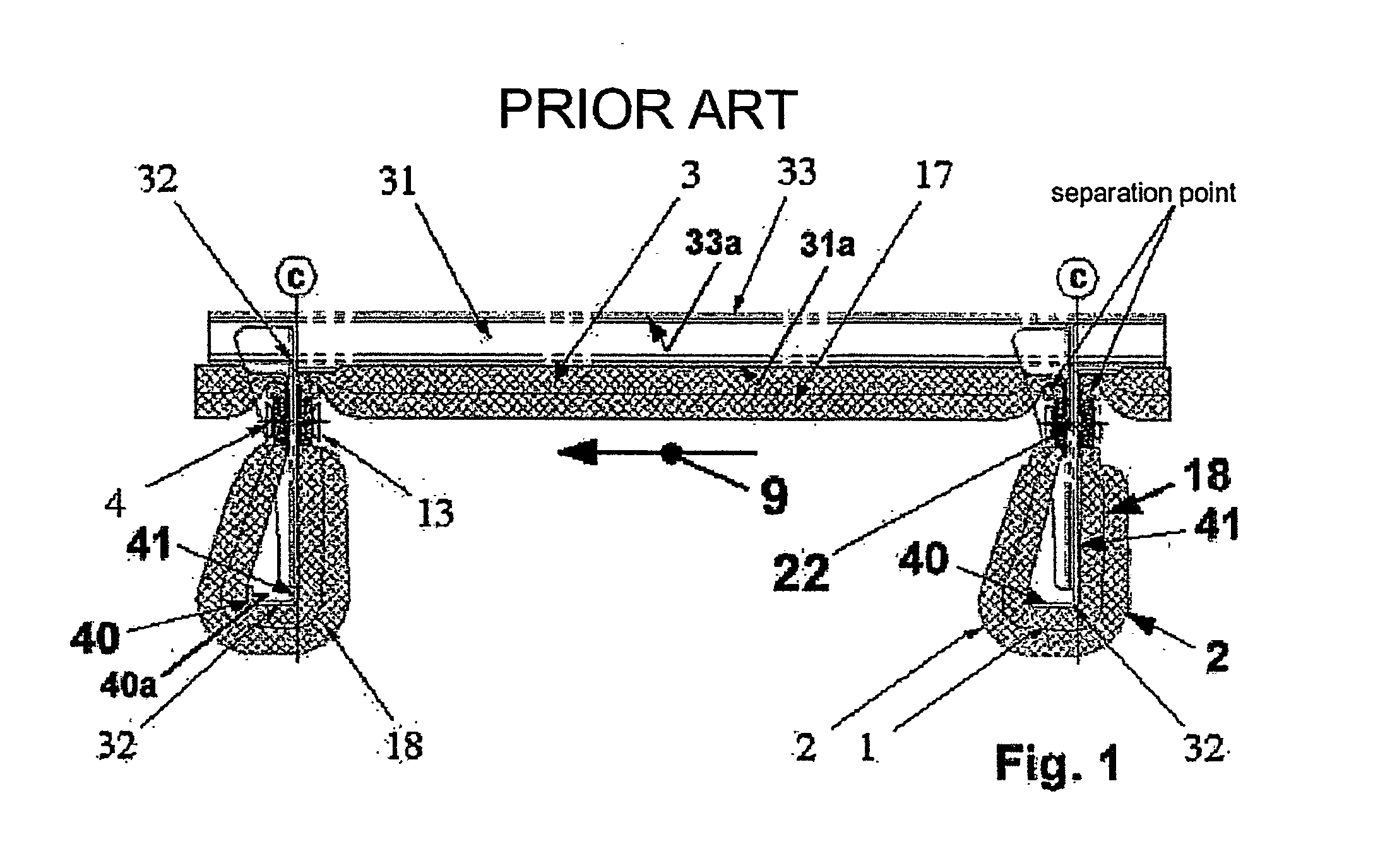
[0025] For greater ease of understanding FIG. 1, which shows an insulation, it should be mentioned by way of an introduction that the structural unit of the aircraft fuselage not only comprises stringers 31 with which all the panels of an outer skin 33 of an aircraft fuselage structure are stiffened, but also comprises several ribs 32 which are arranged perpendicular to the longitudinal axis 9 of the aircraft (approximately) at a distance c, and are attached to the stringer 31. Integrated in these ribs 32, on the unattached end is a (so-called) rib carrier 40 which continues on parallel to the longitudinal axis 9 of the aircraft, wherein the (unattached free) end of the rib carrier 40 (according to this embodiment) is angled perpendicular to the longitudinal axis 9 of the aircraft.

[0026]FIG. 1 shows the position of an insulation package 3 (with general reference characters) (of the fuselage insulation) on the (near) outer skin 33 of the aircraft. In each instance this insulation pa...


PUM


Abstract

The design and attachment of an insulation package according to an exemplary embodiment, which may be installed near the fuselage structure, is believed protect the cabin region of an aircraft against fire whose flames act on the insulation package from outside the aircraft environment, thus clearly facilitating evacuation of the passengers from the vehicle. The insulation package arrangement may comprise several fuselage insulation packages of an elongated form. These packages may adjoin the aircraft fuselage structure in the direction of the longitudinal axis of the aircraft. They may longitudinally adjoin a support surface of the stringers which are attached to the aircraft fuselage, or longitudinally adjoin an inner area of a panel of outer skin and are attached to both longitudinal sides of the ribs. Furthermore, those insulation packages may be completely enclosed by a burn-through-proof foil which is arranged in a space enclosed by interior paneling and by the panels of the outer skin. The design of a fuselage insulation package may be implemented with burn-through-proof insulation of a larger cross section and/or a burn-through-proof barrier layer of a smaller cross section which are arranged within the fuselage insulation package either singly or in combination. In this arrangement, the insulation or the barrier layer extends near to or adjacent to an interior wall region of the foil wall. As an alternative only that insulation which on the longitudinal end of the fuselage insulation package continues outward with a flat insulation end section is attached outside of and adjacent to the foil circumference of the fuselage insulation package. Said end section of insulation is attached to a rib-attachment region which is arranged below the respective longitudinal sides of a rib and near the stringer by means of burn-through-proof attachment elements.

Description

CROSS REFERENCE TO RELATED APPLICATIONS [0001] The present application claims priority of DE 10 2004 001 049 filed Jan. 05, 2004 and U.S. 60 / 600,106 filed Aug. 09, 2004, which are both hereby incorporated by reference.FIELD OF THE INVENTION [0002] The invention relates to an insulation for an aircraft such as a fire insulation or protection. In particular, the present invention relates to an insulation package arrangement for insulating the interior of an aircraft fuselage. BACKGROUND OF THE INVENTION [0003] Conventional insulation systems are known which, as shown in the enclosed FIG. 1, essentially comprise a core- and insulation material which is embedded in an insulation package and comprise an enclosure. The core- and insulation material may comprise products of the fiber industry, of which products in particular glass fiber materials (glass wool) are in widespread use. This material meets to a very large extent the requirements regarding thermal and acoustic insulation. In ord...

Claims


Application Information

Patent Timeline
IPC IPC(8): B64C1/00B64C1/12B64C1/40
CPCA62C2/06B64D25/00B64C1/40A62C3/08
Inventor MULLER, RAINERTURANSKI, PETEROESTEREICH, WILKOREINELT, THORSTEN
Owner AIRBUS OPERATIONS GMBH
Why Eureka
Try Eureka