Coupled ionization apparatus and methods

a technology of coupled ionization and ionization chamber, which is applied in the direction of instruments, particle separator tube details, separation processes, etc., can solve the problem of short life of ion sources, and achieve the effect of high electric field

Active Publication Date: 2006-12-21
INTERLINK ELECTRONICS
View PDF1 Cites 20 Cited by
  • Summary
  • Abstract
  • Description
  • Claims
  • Application Information

AI Technical Summary

Benefits of technology

[0009] Briefly, the invention consists of providing a new distributed plasma ion source as an alternative to point-to-point corona or radioactive ionization sources in ion detection and / or classification instruments. The plasma ion source operates at atmospheric pressure by placing a high RF voltage across two overlapping electrodes separated by a dielectric. With two electrodes, preferably of dissimilar size attached to opposite sides of a thin dielectric, a suitable AC high-voltage signal across the electrodes produces a high electric field along the entire edge of the smaller electrode. The high electric field ionizes the gas sample, and creates the resulting plasma. Thus the shape and circumference of the smaller electrode can control the quantity of plasma that is produced. The ionized molecules that are formed are dependent upon the reaction region configuration.

Problems solved by technology

It is similar to corona but without the corona point erosion and instability leading to a short ion source lifetime.

Method used


Image

  • Coupled ionization apparatus and methods
  • Coupled ionization apparatus and methods
  • Coupled ionization apparatus and methods

Examples


experimental examples

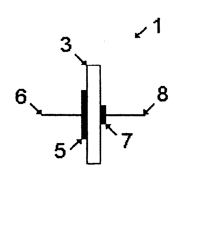
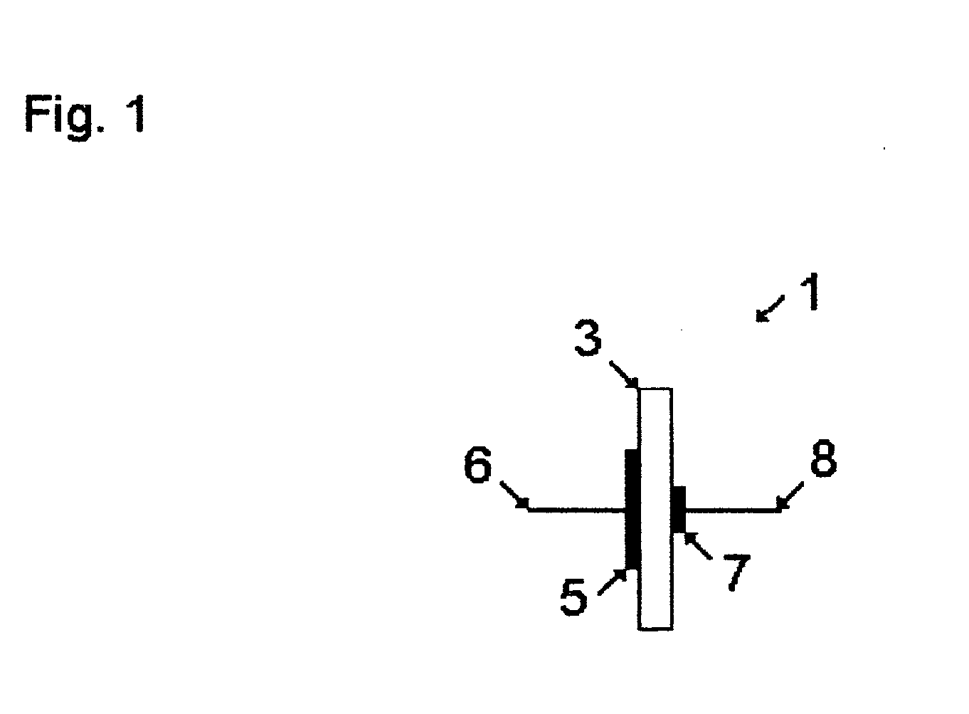
[0028] An RF voltage was placed across two electrodes separated by a dielectric (glass slide) to create the new plasma ion source. Several configurations were investigated and two seemed to work better than the rest. These plasma ion sources were placed in front of a mass spectrometer to study the ions produced. The open plasma ion source was then monitored over time to investigate long term stability. The enclosed plasma ion source was interfaced to the mass spectrometer and explosives were introduced to study ion formation with different reactant ions.

[0029] Each open plasma ion source was a glass slide with a large and small electrode drawn on either side with a silver conductive pen. The small electrode was coated with hydrogen hexachloroplatinate (IV) to provide a platinum coating. Another slide had no coating. After 17 hours of use, discoloration could be seen around the edge of the uncoated smaller electrode where it was glowing. Both sources were run for approximately 80 ho...


PUM


Abstract

Apparatus for generating ions in a gaseous medium, the apparatus including two electrodes separated by a dielectric material and a means for generating radio frequency pulses. The electrodes are of dissimilar size and are attached to opposite sides of the dielectric material. The smaller electrode shape and circumference is configured to control the quantity of plasma that is produced. Method of generating ions in a gaseous medium having the step of applying a radio frequency voltage between two electrodes separated by a dielectric material so as to generate a plasma ion source. Locating the plasma ion source in a confined area to yield NO3-ions. Locating the plasma ion source in an open configuration to yield predominantly CO3-ions with minor amounts of O2- and O3-ions.

Description

REFERENCE TO RELATED APPLICATIONS [0001] This is a continuation in part of Provisional Application Ser. No. 60 / 531,768, filed 22 Dec. 2003.BACKGROUND OF THE INVENTION [0002] This invention pertains to methods and apparatus for using the polarity reversals of a confined plasma, or similar electrode on one side of a dielectric, to generate useful ions and ionized molecules with a plasma around an electrode external to the confining dielectric, thus, being a plasma Ion Source; and a method and apparatus for the separation of these ions and molecules according to their polarity by use of an electric field; and a method and apparatus to couple or make available the selected polarity of the separated ions and molecules to a detection system. Thus, these Coupled Ionization Apparatus and Methods provide a novel ionizer and the techniques for interfacing the ionizer to chemical detection systems. Among detection systems that could be attached to and use this ion generator are, but not limite...

Claims


Application Information

Patent Timeline
Patent Type & Authority Applications(United States)
IPC IPC(8): H01T23/00
CPCH01J49/0018H01T23/00H01J49/168H01J49/10
Inventor BLANCHARD, WILLIAM C.
Owner INTERLINK ELECTRONICS
Why Eureka
Try Eureka