
Digital telecommunications call management and monitoring system

Active Publication Date: 2006-12-21
GLOBAL TELLINK
View PDF20 Cites 116 Cited by
  • Summary
  • Abstract
  • Description
  • Claims
  • Application Information

AI Technical Summary

Benefits of technology

[0063] A second method of detection involves the analysis of the time of flight of the emitted RF pulse. This method requires the same sensor configuration as the triangulation method. In this method, the sensor measures the time it takes each pulse to arrive at the sensor location as compared to the pulses that occur at a regular rate in an active RF device. From this data, the analyzing system can determine an accurate distance from the sensor that the user must be located within some minor degree of error. By combining this information from a multitude of sensors, the location of the person can triangulated.
[0065] It is advantageous to use active RF bands because they are very accurate for determining the location of an individual. However, most active systems have a relatively short battery life and require constant recharging. A passive RF device may also be used with only slight modification to the system. A passive RF device works by emitting a pulse only when activated by some other emitted pulse. In this embodiment, the sensors may also be equipped with RF pulsing devices designed to activate the user's RF devices. When a user attempts to access a telephone terminal, the system sends out a pulse. As a result, the user's RF device is activated and the person using the telephone terminal is authenticated. The user's specific user options can then be forwarded to the telephone terminal the user is utilizing.
[0075] An additional security means incorporated in the present invention is the locking of the telephone keypad after a connection is made. This prevents the caller from possibly dialing out to a third party that has not been approved after a pre-approved connection has been made. Alternatively, the system may allow the user to press a pre-determined number of keys after a connection has been made. This allows an authorized user to access an automated service and enter menu selection keys.
[0077] Therefore, it is an object of the present invention to provide an efficient and reliable user identification system through use of such means as personal identification numbers (PIN), radio frequency identification (RFID) technology, and biometric measures.
[0084] Yet a further object of the present invention is to provide a means of restricting communication options to certain users.
[0089] Still another object of the present invention is to provide a digital call management system where no degradation of service or capability occurs regardless of whether the system is located on or off site.

Problems solved by technology

Otherwise, unaccountable telephone costs would severely hinder the availability of the telephone systems in institutions.
Thus, the communication system used in a regulated institution must employ unique functions often unnecessary in other types of institutions.
Generally, these simple systems are not equipped to restrict an inmate from calling an individual.
Without the necessary constraints on an inmate's use of the telephone system, inmates have often harassed outside parties or individuals.
However, a primary problem with this identification method is the ease of obtaining another inmate's PIN.
For example, individuals who commonly forget their PIN may write it down, increasing the possibility that an unauthorized individual will view the PIN and use it.
In addition, if a PIN number is compromised and utilized by an unauthorized inmate, the unauthorized inmate may then be able to call certain individuals who are restricted to that inmate, since the unauthorized inmate is no longer using the proper PIN associated with that inmate.
In known systems, the PIN identification method is incapable of verifying that the individual who supplies the PIN is the actual specified inmate.
This method, however, provides only minimal additional protection because a debit card and its associated PIN can often easily be taken from another inmate, or given to another inmate.
This provides an additional security measure, but again is minimally secure because such information can easily be obtained in a correctional facility.
The system may also limit the amount of time each inmate / user is permitted to conduct each outbound telephone call through the system.
For example, if an inmate misbehaves, the inmate's telephone privileges may be further limited or revoked completely.
It is also foreseeable that the telephone numbers of the family members of these specific individuals may also be blocked.
Some current systems also limit the use of specific long-distance carriers.
This feature prevents inmates from interacting with telephone games and lotteries, and in certain older systems, prevents the inmate from achieving an unrestricted dial tone.
However, systems known in the art have only used biometrics to a limited extent.
The system attempts to locally automate and simplify the process of payment for routing calls without live operator assistance, but does not address additional security concerns that may exist in specific facilities, such as in a penal institution.
Furthermore, it does not provide for protection measures to confirm that the individual supplying the account number is the individual entitled to the use of the account.
Additionally, the system does not provide any means of monitoring the conversations taking place or restricting which individuals are accessed by the user.
However, the system does not teach a means for selecting the call type or a call monitoring means.
It also fails to teach an advanced verification means specific to a user.
The system fails to provide a selection means for the user, such as the ability to choose the type of call to be placed (e.g., collect, debit, international, etc.).
It also fails to teach any call monitoring means and would therefore be unacceptable as a communication system for a penal institution.
However, it does not teach a commissary system for use with a PSTN.
This system also fails to teach multiple authentication means and would therefore be unacceptable for use in a penal institution.
However, the system does not allow for other types of calls, such as collect calls, to take place.
Furthermore, it fails to provide an advanced call monitoring apparatus with an advanced authentication apparatus.
However, it does not identify or verify the individual speaking.
Furthermore, this system does not provide a means to identify the user or verify that the user is not partaking in fraudulent activities.
It also fails to teach of a monitoring and call control means.
However, the system fails to disclose a means for incorporating biometric recognition in an institution telephone call system.
Furthermore, it fails to disclose a means for incorporating a WAN-based institution telephone control system.
The system disclosed is further limited by its lack of telephone call monitoring ability and calling party identification means, and is therefore unsuitable for use in penal institutions.
However, the system fails to implement additional biometric means useful in identifying a called party and fails to apply these features to specific institutional functions.
It is limited by detection of certain sounds which may not be readily machine-recognizable.
For example, it is foreseeable that interference, background noise, or compressed voice data may inhibit the detection of the tones.
However, it would be too costly to implement such a system in a penal institution or similar facility.
Additionally, the system does not consider possible payment methods for calls or call management.
Although it contemplates other voice recognition methods, the system fails to address any other field of biometric recognition.
The invention is further limited by its inability to manage call restrictions and lacks monitoring capabilities.
However, it does not address restrictions to the system or further monitoring means during use of the system, which are essential for systems within a penal institution.
The system is limited in its ability for use in a telephonic system in a penal institution by the lack of monitoring or call management abilities.

Method used


Image

  • Digital telecommunications call management and monitoring system
  • Digital telecommunications call management and monitoring system
  • Digital telecommunications call management and monitoring system

Examples


Embodiment Construction

[0097] As required, a detailed illustrative embodiment of the present invention is disclosed herein. However, techniques, systems and operating structures in accordance with the present invention may be embodied in a wide variety of forms and modes, some of which may be quite different from those in the disclosed embodiment. Consequently, the specific structural and functional details disclosed herein are merely representative, yet in that regard, they are deemed to afford the best embodiment for purposes of disclosure and to provide a basis for the claims herein, which define the scope of the present invention. The following presents a detailed description of the preferred embodiment (as well as some alternative embodiments) of the present invention.

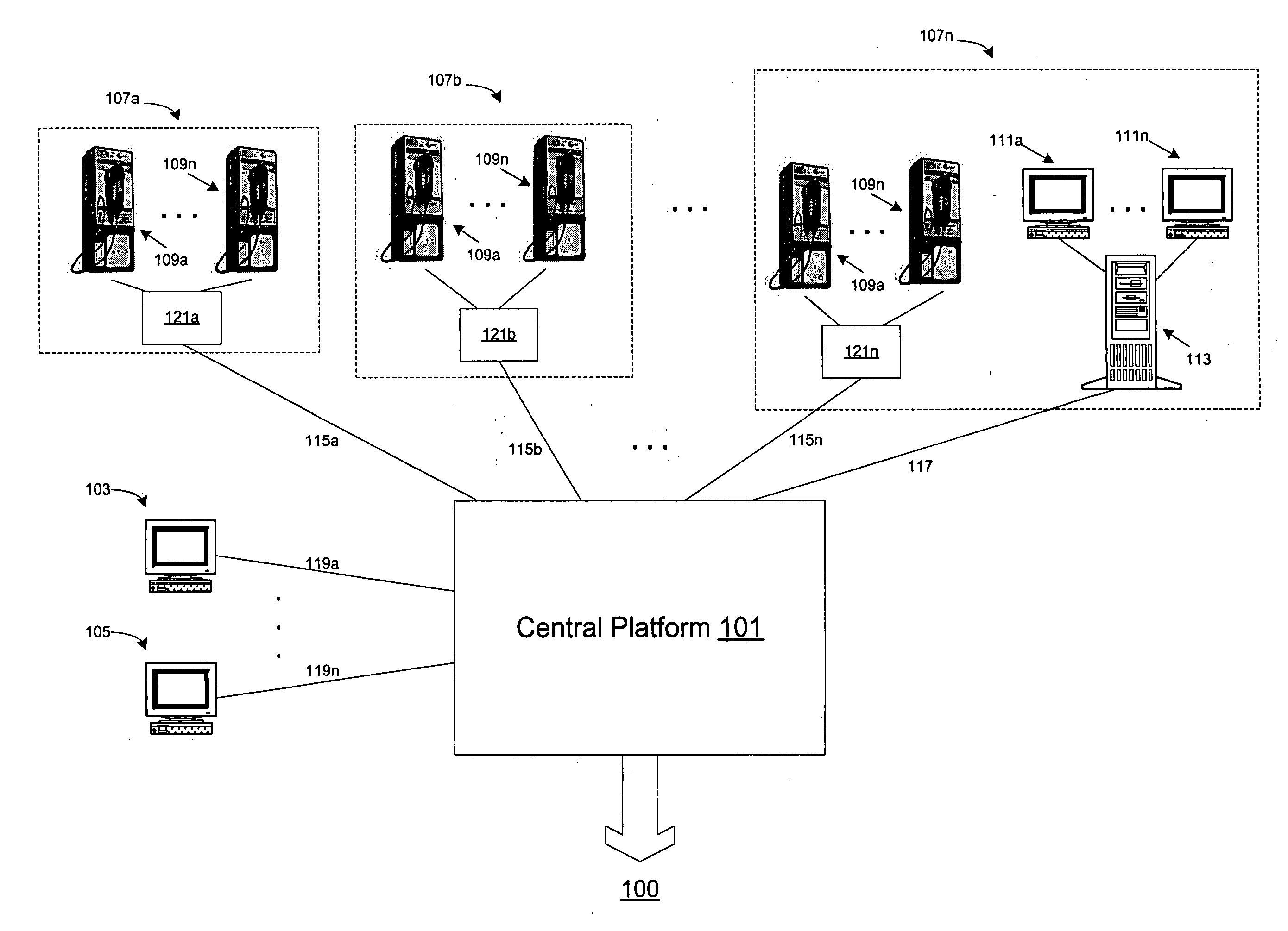
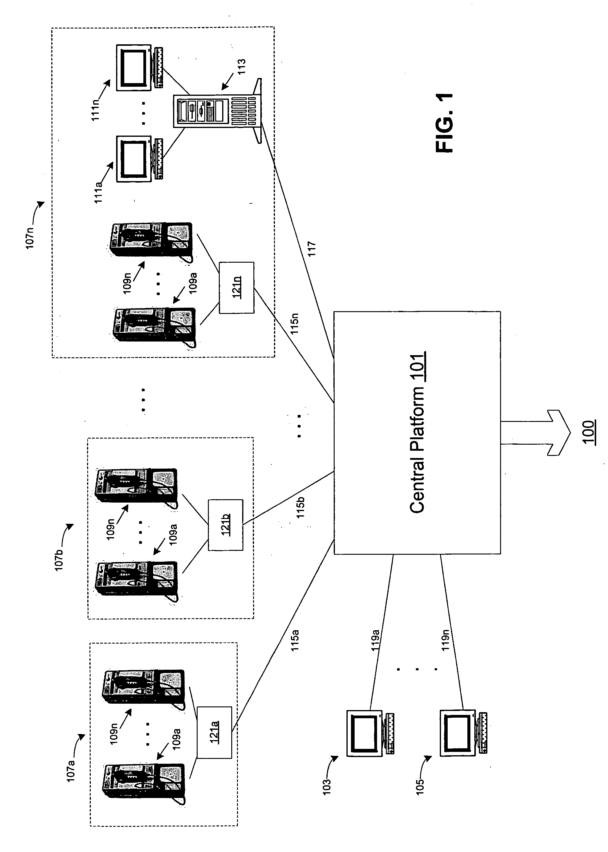
[0098] Referring first to FIG. 1, depicted is a block diagram of the preferred embodiment of the present invention showing the centralized set up of the call management system operating over a PSTN. The central call management platform...


PUM


Abstract

The present invention discloses a centralized, digital, computer-based telephone call management system for authenticating users of a telephone system in an institutional facility. The system includes the capacity to allow an institution to control, record, monitor, and bill and report usage and access to a telephone network. The telephone call management system further includes both accounting and management software for use in controlling, monitoring, billing, recording, and reporting usage and access. Also, it can operate over both a Public Switch Telephone Network (PSTN) and a Voice over Internet Protocol (VOIP) infrastructure.

Description

FIELD OF THE INVENTION [0001] The present invention relates generally to the field of telephone communication systems in penal institutions or similar facilities. In particular, the present-invention relates to a centralized, fully self-contained, digital, computer-based telecommunication system with the capacity to allow an institution to control, record, monitor, and report usage and access to a telephone network. BACKGROUND OF THE INVENTION [0002] Generally, the need to monitor, control, record and provide detailed records of the usage of a telephone system in a controlled institutional environment is well recognized. It is common to utilize a controlled telephone system capable of monitoring outgoing telephone connections in many types of institutional environments, including penal institutions, military institutions, hospitals, schools, businesses, specific types of government institutions, etc. The reasons for monitoring and controlling institutional telephone systems are evid...

Claims


Application Information

Patent Timeline
IPC IPC(8): H04M3/08
CPCH04M15/00H04M3/2281H04L63/304H04L63/306H04M3/42221H04M3/385H04M7/006H04M2203/301H04M2203/551H04M2203/6054
Inventor HODGE, STEPHEN
Owner GLOBAL TELLINK
Learn More