
Method of manufacturing rapid prototyping workpiece by using laser transfer printing technology

a technology of laser transfer printing and workpieces, applied in the direction of manufacturing tools, recording devices, instruments, etc., can solve the problems of cnc carving, cnc carving also has limitations on molding, sla method still, etc., to facilitate the next loop of actions, save work hours, materials and costs, and enhance the precision of the workpiece

Inactive Publication Date: 2006-12-28
NAT CHENG KUNG UNIV
View PDF4 Cites 10 Cited by
  • Summary
  • Abstract
  • Description
  • Claims
  • Application Information

AI Technical Summary

Benefits of technology

[0038] It is a primary objective of the present invention to provide a method of manufacturing rapid prototyping workpiece, characterized in that a laser beam or other light is projected onto the photo-conductive drum to attach powder materials to form a thin layer, and then the thin-layer material is coated on a working platform. A point, line or plane light source of stronger intensity is used to go with go with the DMD (Digital Micromirror Device) or LCD (Liquid Crystal Display) to scan or project the point, line or plane light source for a selective exposure and produce a physical change or a chemical change in the selected projecting region and combine the materials to become an acceptable property. The method comprises three stages of a process and repeats the process to complete a physical workpiece.
[0042] The whole manufacturing process uses this method to stack layer by layer to build a complete three-dimensional physical workpiece, so as to achieve the effect of saving work hours, materials and costs as well as enhancing the precision of the workpiece. The invention is definitely a very valuable manufacturing method.

Problems solved by technology

However, traditional handmade mold requires experienced technicians and is not as precise, and CNC carving also has limitations on the molding, clamping tools and knife tools.
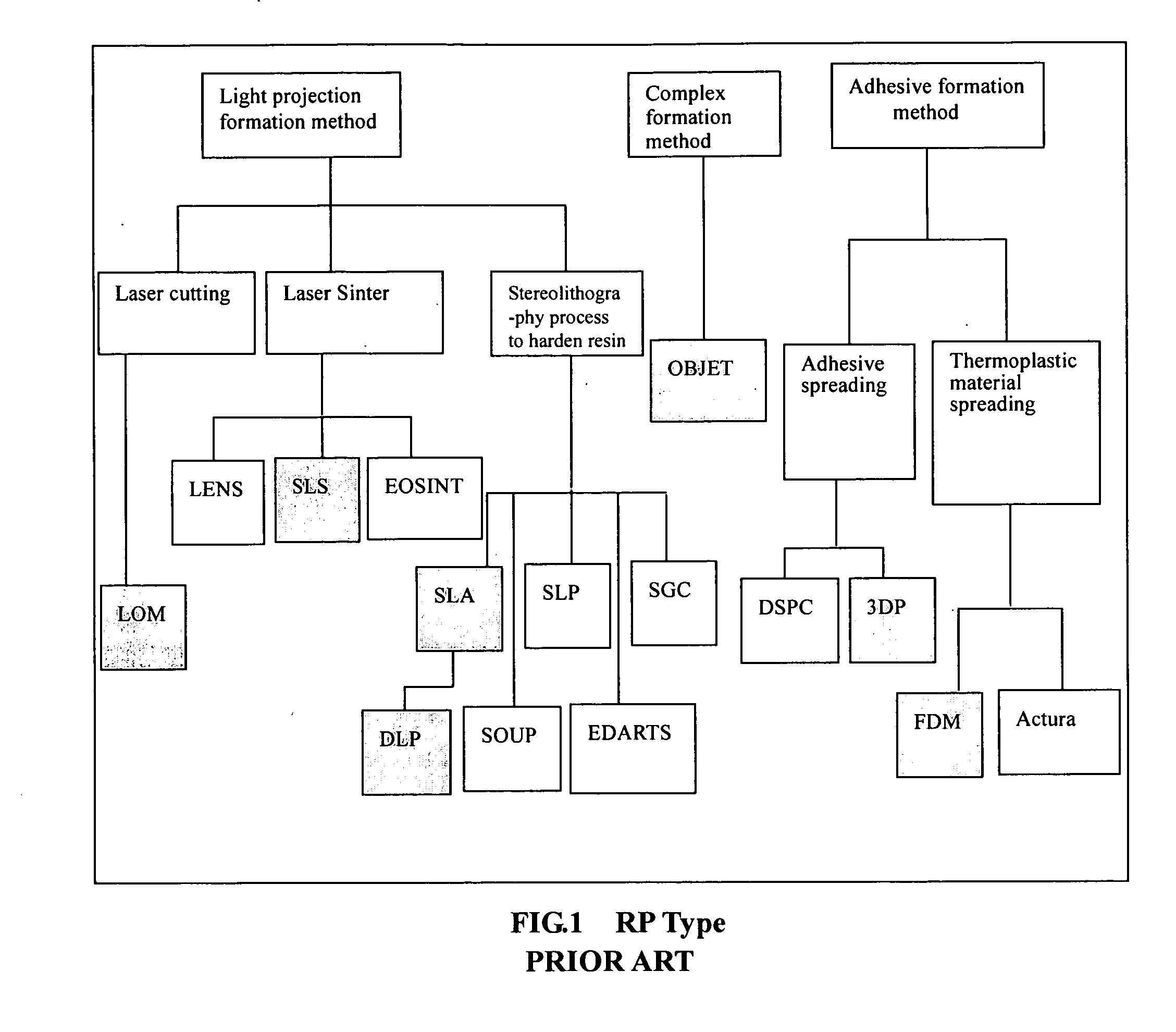
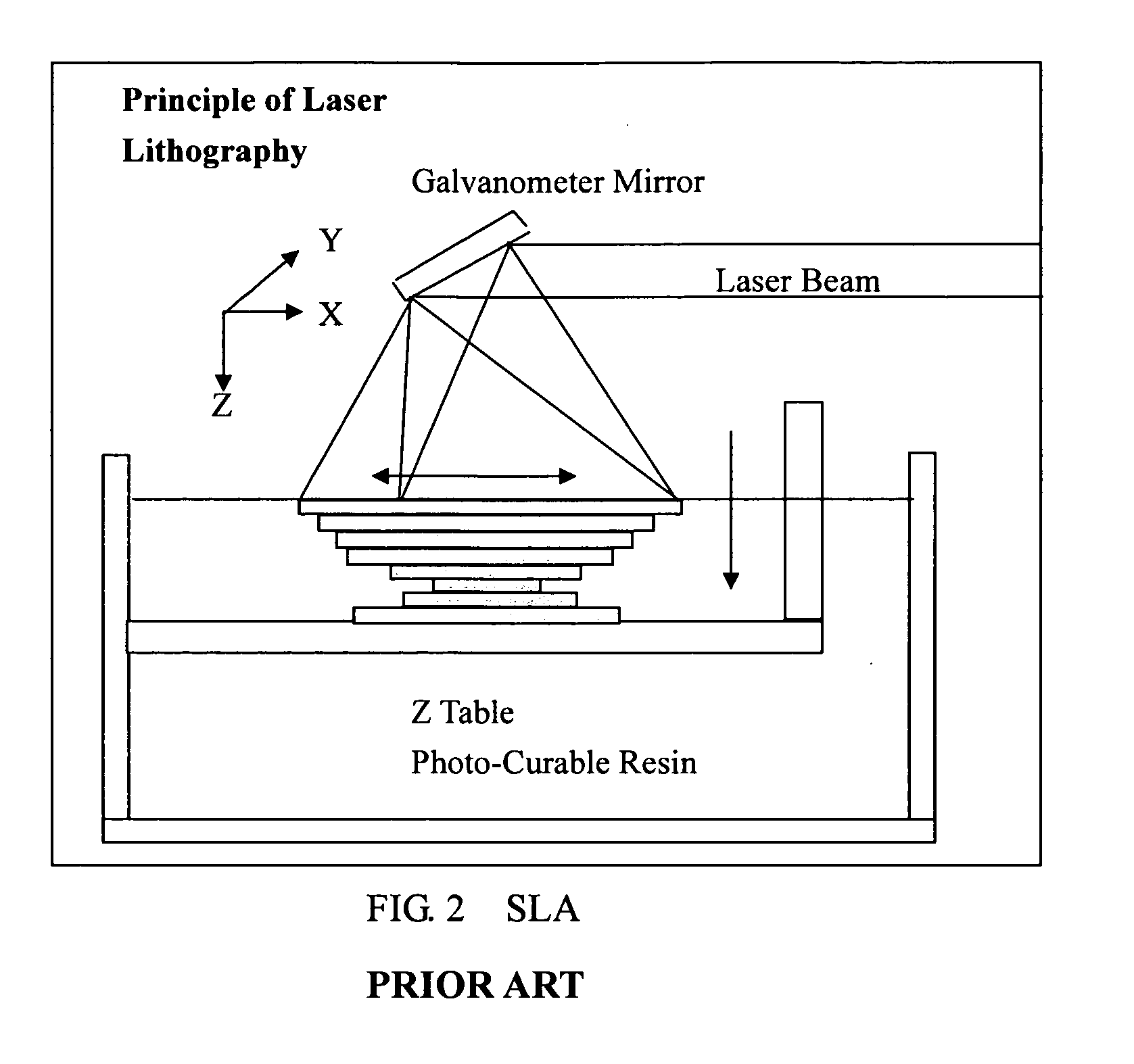
However, the SLA method still has the following issues:
b. Since its material is a liquid resin and it is necessary to prepare buckets to fill up with the materials for making the workpiece, therefore it requires more materials and incurs a higher cost.
a. Roller or scraper is used to coat powder, and thus the density of powder will be uneven.
c. Powder causes dusts easily, which is harmful to human body.
d. Powder is hard to be heated evenly.
e. This manufacturing process cannot be applied easily for large workpiece.
The major drawback of this method resides on a poor surface coarseness and its need of building supports. FIG. 4 shows a drawing related to the structure and principle of FDM.
b. It has a poor precision.
d. It is not easy to spread the powder with an even density.
The molecules of the material used in this method are linked with each other, and it is necessary to prepare each layer material before the manufacture, and thus the preparation is more complicated.
Furthermore, the major drawback of this manufacturing process resides on the difficulty of obtaining additional material.
If the nozzle is not controlled properly, then the precision of the finished goods will become low.
However, the cost for a high-precision nozzle is very high, and such nozzle gets clogged very easily, and thus greatly increasing the cost.
Using laser as an activation source incurs a higher cost, and the DLP uses the light emitted from halides and the DMD (Digital Micromirror Device) controls whether or not to project the light onto the curing adhesive resin.
Since the prepared material is a liquid resin and it requires buckets to fill up the material for manufacturing the workpiece, therefore it requires more materials and a higher cost for the manufacturing.
The precision is completely controlled by the DMD, and thus the precision of the DMD is extremely high and directly affects the manufacturing cost.
The low-density light source provided by DMD is easily affected by the light in the environment, and thus material stored in a large bucket may be deteriorated easily, which makes the storage of raw material very easy.
Since the projecting area is larger and the intensity of the light source is insufficient, the substrate is not reacted completely and its strength will not be strong enough.
However, it has a weak strength similar to a ceramic sintered by dry mud.
However, this kind of manufacturing process mainly uses ceramic mud technology for manufacturing ceramic workpieces, but it is not applicable for a general rapid prototyping workpiece.

Method used


Image

  • Method of manufacturing rapid prototyping workpiece by using laser transfer printing technology
  • Method of manufacturing rapid prototyping workpiece by using laser transfer printing technology
  • Method of manufacturing rapid prototyping workpiece by using laser transfer printing technology

Examples


Embodiment Construction

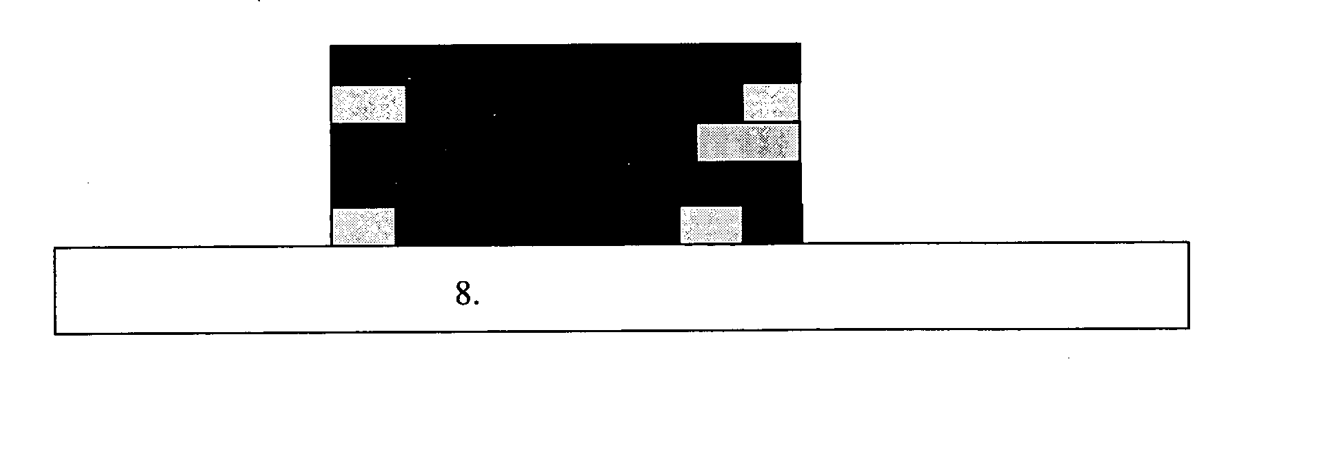
[0073] Referring to FIG. 9 for the manufacturing process employing the method of manufacturing rapid prototyping workpiece in accordance with the present invention, the basic manufacturing procedure is described as follows: [0074] Step 1: An electric roll spreads the static electricity evenly to the surface of photo-conductive drum. [0075] Step 2: A laser beam or a visible light is projected onto the photo-conductive drum to conduct its electric charges and lower its electric potential. [0076] Step 3: When the photo-conductive drum rolls through the material cartridge, the material produces an electric attraction due to the potential difference and is attached onto the section exposed by the photo-conductive drum. [0077] Step 4: Use an insulating scraper to scrap the excessive thickness of the attached material. [0078] Step 5: Use an appropriate method to transfer the material printed on the photo-conductive drum to the working platform. [0079] Step 6: A point, line or plane light s...


PUM

PropertyMeasurementUnit
electric potentialaaaaaaaaaa
thicknessaaaaaaaaaa
pressureaaaaaaaaaa

Abstract

The invention discloses a method of manufacturing rapid prototyping workpiece by projecting a laser beam or other light onto the photo-conductive drum to attach powder materials to form a thin layer, and then coat the thin-layer material on a working platform. A point, line or plane light source of stronger intensity is used to go with the DMD (Digital Micromirror Device) or LCD (Liquid Crystal Display) to produce a physical change or a chemical change in the selected projecting region and combine the materials to become an acceptable property. The method comprises three stages of a process and repeats the process to complete a physical workpiece. The first stage refers to evenly spreading electric charges on a photo-conductive drum, and then projects a laser beam or a visible light onto the photo-conductive drum to electically conduct the electric charges and lower the electric potiential. By that time, the photo-conductive drum rotated in a high speed passes through a cartridge containing powder, the material will be attached onto the photo-conductive drum, since there is a potential difference between the photo-conductive drum and the material. Then, an appropriate method is used to flatly coat the material disposed on the photo-conductive drum onto the working platform, and thus a very thin even material layer is formed. The second stage refers to using a point, line or plane light source of stronger intensity for a selected region to go with a DMD or LCD to project or scan the selected region and produce a physical or chemical change, so that the materials are combined with each other to form an acceptable property. The third stage refers to removing the material remained on the photo-conductive drum and eliminating the static charges on the photo-conductive drum, so that the electric potential at the surface of the photo-conductive drum resumes its initial state to facilitate the next loop of actions. The whole manufacturing process uses this method to stack layer by layer to build a complete three-dimensional physical workpiece, so as to achieve the effect of saving work hours, materials and costs as well as enhancing the precision of the workpiece. The invention is definitely a very valuable manufacturing method.

Description

BACKGROUND OF THE INVENTION [0001] 1. Field of the Invention [0002] The present invention generally relates to a method of manufacturing rapid prototyping workpiece, and more particularly to a manufacturing process that uses the static electricity of a photo-conductive drum as the driving force and applies such to rapidly manufacture a three-dimensional physical workpiece. The process starts with charging the photo-conductive drum fully, and then projects a laser beam or a visible light on the photo-conductive drum to electrically conduct its electric charges and lower the electric potential. The photo-conductive drum is rotated in a high speed and powders will be attached onto the photo-conductive drum when it passes through a material cartridge, and then an appropriate method is used to evenly transfer print and attach the material of the photo-conductive drum onto a working platform. A light source with strong intensity is used for the regions selected by the system, and a DMD or...

Claims


Application Information

Patent Timeline
Patent Type & Authority Applications(United States)
IPC IPC(8): B41J2/435
CPCG03G16/00B29C67/0066B29C64/135
Inventor HWANG, SHENG-JYELEE, SEN-YUNGLAI, WEI-HSIANCHENG, CHUN-IWANG, MUH-RONGWANG, CHUN-SHANCHEN, CHUH-YUNGCHEN, CHIEH-LIHSIEH, CHENWANG, CHENG-CHIENLEU, TZONG-SHYNG
Owner NAT CHENG KUNG UNIV
Learn More