
Optical delay line in holographic drive

Inactive Publication Date: 2006-12-28
AKONIA HOLOGRAPHICS
View PDF41 Cites 31 Cited by
  • Summary
  • Abstract
  • Description
  • Claims
  • Application Information

AI Technical Summary

Benefits of technology

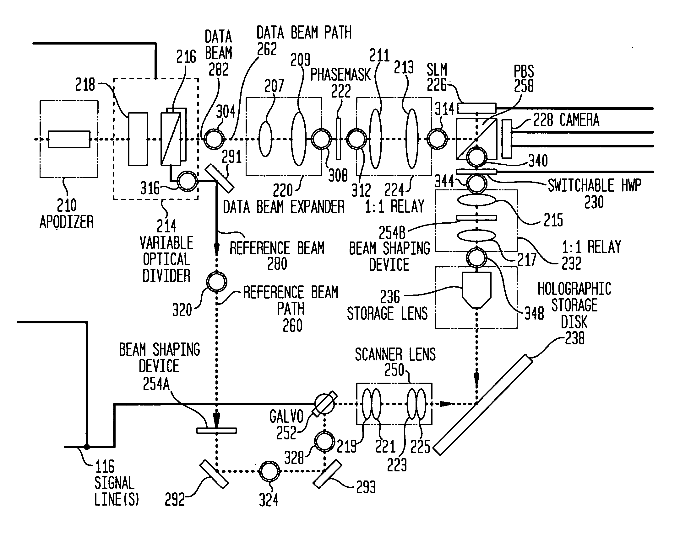
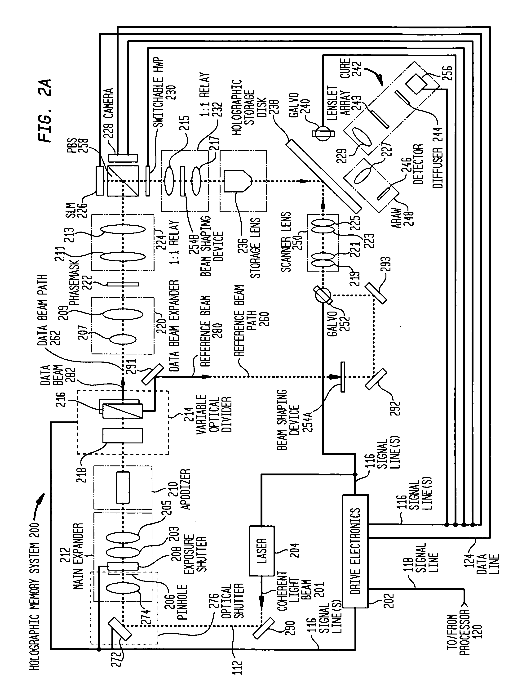
[0012] wherein one of the data beam and reference beams paths comprise an optical delay line so that th

Problems solved by technology

This optical path length difference may adversely affect the relative coherence of the interfering beams, and subsequently weaken the interference patterns recorded by the holographic medium, for example, when holographic digital data is recorded, making the recorded hologram difficult to read or unreadable.
To avoid such adverse effects the interference pattern that may be caused by optical path length differences between the data beam and reference beam paths, operating constraints may need to be imposed on the holographic data storage system that may make the system less flexible and robust.

Method used


Image

  • Optical delay line in holographic drive
  • Optical delay line in holographic drive
  • Optical delay line in holographic drive

Examples


Embodiment Construction

[0028] It is advantageous to define several terms before describing the invention. It should be appreciated that the following definitions are used throughout this application.

DEFINITIONS

[0029] Where the definition of terms departs from the commonly used meaning of the term, applicant intends to utilize the definitions provided below, unless specifically indicated.

[0030] For the purposes of the present invention, the term “light source” refers to any source of electromagnetic radiation of any wavelength. The light source of the present invention may be from a laser, one or more laser diodes (LDs), etc. Suitable light sources for use in embodiments of the methods and systems of the present invention include, but are not limited to, those obtained by conventional laser sources, e.g., the blue and green lines of Ar+ (458, 488, 514 nm) and He—Cd lasers (442 nm), the green line of frequency doubled YAG lasers (532 nm), and the red lines of He—Ne (633 nm), Kr+ lasers (647 and 676 nm), ...


PUM


Abstract

The present invention relates to a system comprising a holographic data storage drive that records holographic digital data in a holographic recording medium, and which comprises: a data beam path having a first optical path length; and a reference beam path having a second optical path length; wherein one of the data beam and reference beams paths comprise an optical delay line so that the difference between the first and second optical path lengths is less than the laser coherence length. The present invention further relates to a method for operating a laser in the holographic data storage drive in a multi-mode state during the recording of holographic digital data the holographic medium without adverse effects on the strength of the interference patterns formed.

Description

CROSS-REFERENCE TO RELATED APPLICATIONS [0001] This application makes reference to and claims the benefit of the following co-pending U.S. Provisional Patent Application No. 60 / 684,531 filed May 26, 2005. The entire disclosure and contents of the foregoing Provisional Application is hereby incorporated by reference. This application also makes reference to the following co-pending U.S. patent applications. The first application is U.S. App. No. [INPH-0007-UT1], entitled “Illuminative Treatment of Holographic Media,” filed May 25, 2006. The second application is U.S. App. No. [INPH-0007-UT2], entitled “Methods and Systems for Laser Mode Stabilization,” filed May 25, 2006. The third application is U.S. App. No. [INPH-0007-UT3], entitled “Phase Conjugate Reconstruction of Hologram,” filed May 25, 2006. The fourth application is U.S. App. No. [INPH-0007-UT4], entitled “Improved Operational Mode Performance of a Holographic Memory System,” filed May 25, 2006. The fifth application is U.S...

Claims


Application Information

Patent Timeline
IPC IPC(8): G02B5/32
CPCG02B17/023G03H1/02G03H2001/0212G11B7/1362G03H2223/26G11B7/0065G11B7/1359G03H2222/22
Inventor REDMOND, IAN R.FABINY, LARRYKRNETA, VLADIMIRRILEY, BRIAN S.
Owner AKONIA HOLOGRAPHICS
Learn More