Apparatus for illuminating a surface

a surface and apparatus technology, applied in the direction of instruments, condensers, laser details, etc., can solve the problems of disadvantages, different divergence of fast axis and slow axis, poor collimatability of laser light emanating from qcw bars, etc., to achieve the effect of substantially improving the ability to be used as a free emitter or for illuminating a surface, improving beam quality and improving collimatability

Inactive Publication Date: 2006-12-28
LIMO PATENTVERWALTUNG GMBH & CO KG
View PDF4 Cites 22 Cited by
  • Summary
  • Abstract
  • Description
  • Claims
  • Application Information

AI Technical Summary

Benefits of technology

[0006] It has surprisingly been shown that despite the overlapping of the laser light of adjacent emitters only comparatively slight losses occur before the impingement on the beam transforming means when using beam transforming means in the case of semiconductor laser bars with a short spacing between the individual emitters, that is to say in the case of QCW bars, for example. The losses occurring in the beam transforming means owing to the prior overlapping are, for example, less than 5%. The collimatability, and thus the ability to be used as a free emitter or for illuminating a surface can thereby be substantially improved owing to the use, which is surprisingly possible in this way, of beam transforming means, even for QCW bars.
[0007] It can be provided that the illuminating apparatus comprises homogenizer means for homogenizing the laser light emerging from the emitters. Owing to the use of homogenizer means, the homogeneity and thus the beam quality can be substantially improved such that a surface far removed from the apparatus can be illuminated very uniformly.
[0008] The uniform illumination of a surface far removed from the apparatus can be applied in multifarious ways. Examples are glare-free night vision systems in road traffic and rail traffic, as well as, in the field of metrology, digital image acquisition for production control of packaging such as, for example, foodstuffs packaging. A range of advantages result from the uniform illumination of the surface and from the better collimatability owing to the apparatus according to the invention. The intensity distribution in the region of the illuminated surface has very steep edges, and so it is possible to achieve a higher intensity in the illuminated region, because only a very slight power loss occurs in the adjacent regions. It is possible in this way to reduce the power consumption of the illuminated system, or to reduce the number of emitters or semiconductor laser bars. Furthermore, the more homogeneous intensity distribution leads to a better image contrast and permits the use of cameras that are more cost-effective in the case of digital image acquisition, for example.
[0009] It can be provided that the homogenizer means are of multistage design. It can be provided here in particular, that the number of stages of the homogenizer means for homogenizing with regard to the first direction is greater than that for homogenizing with regard to the second direction. Since the laser light has a substantially better collimatability with regard to the second direction, or with regard to the fast axis, one homogenizer stage for the fast axis proves to be sufficient as a rule. The use of one stage for the fast axis and two stages for the slow axis results in a substantially lower outlay on application than in the case of a completely two-stage homogenizer. The reason for this is that the spacing between the two homogenizers must be adjusted relative to one another only with regard to one axis, namely with regard to the slow axis. The spacing of the homogenizers can be optimally adapted in this way to the requirements with regard to the slow axis. Furthermore, there is a lowering of the requirements placed on the focal length tolerances of the lenses or the like used for the homogenizers.

Problems solved by technology

Nevertheless, the laser light emerging from the semiconductor laser bar is more difficult to collimate with regard to the slow-axis direction because, firstly, the emitters are extended in this slow-axis direction and, secondly, because a complete row of emitters is arranged next to one another.
Such arrangements have not yet been implemented in the case of QCW bars, and so the collimatability of the laser light emanating from QCW bars is very poor.
Furthermore, in the case of the use of a semiconductor laser bar for illuminating a surface or for operating a free emitter, the different divergence of fast axis and slow axis and / or the poor collimatability of the slow axis turn out to be disadvantageous.

Method used


Image

  • Apparatus for illuminating a surface
  • Apparatus for illuminating a surface
  • Apparatus for illuminating a surface

Examples


Embodiment Construction

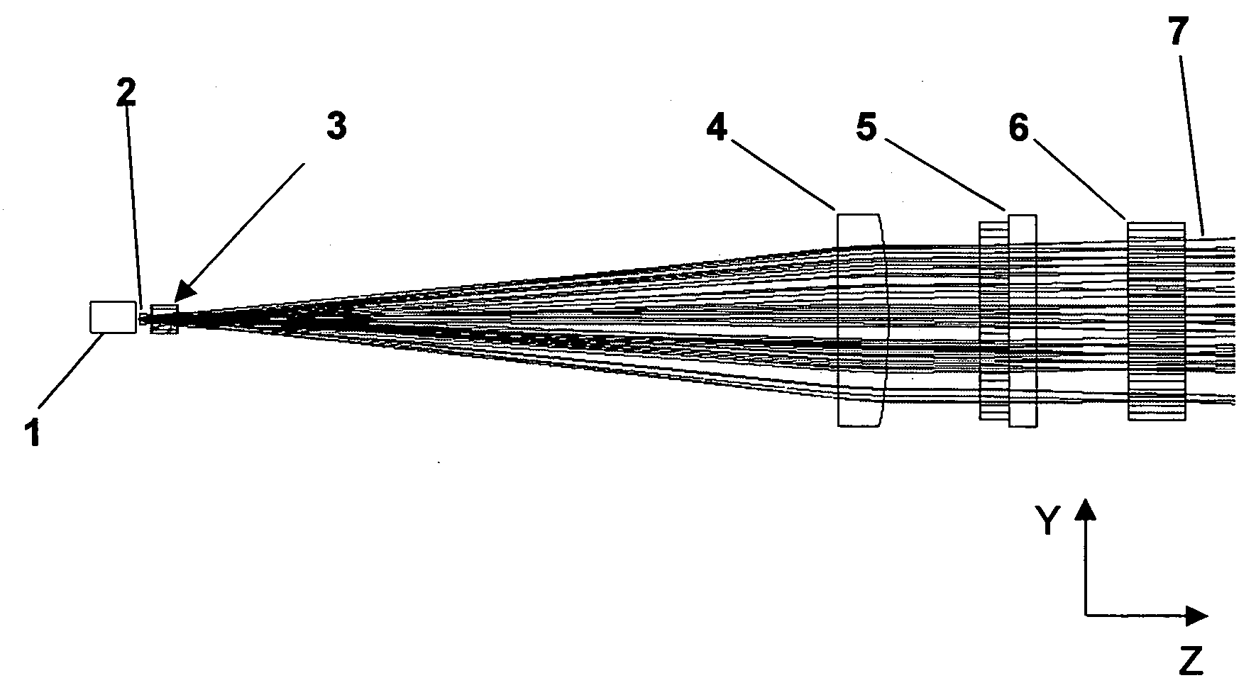
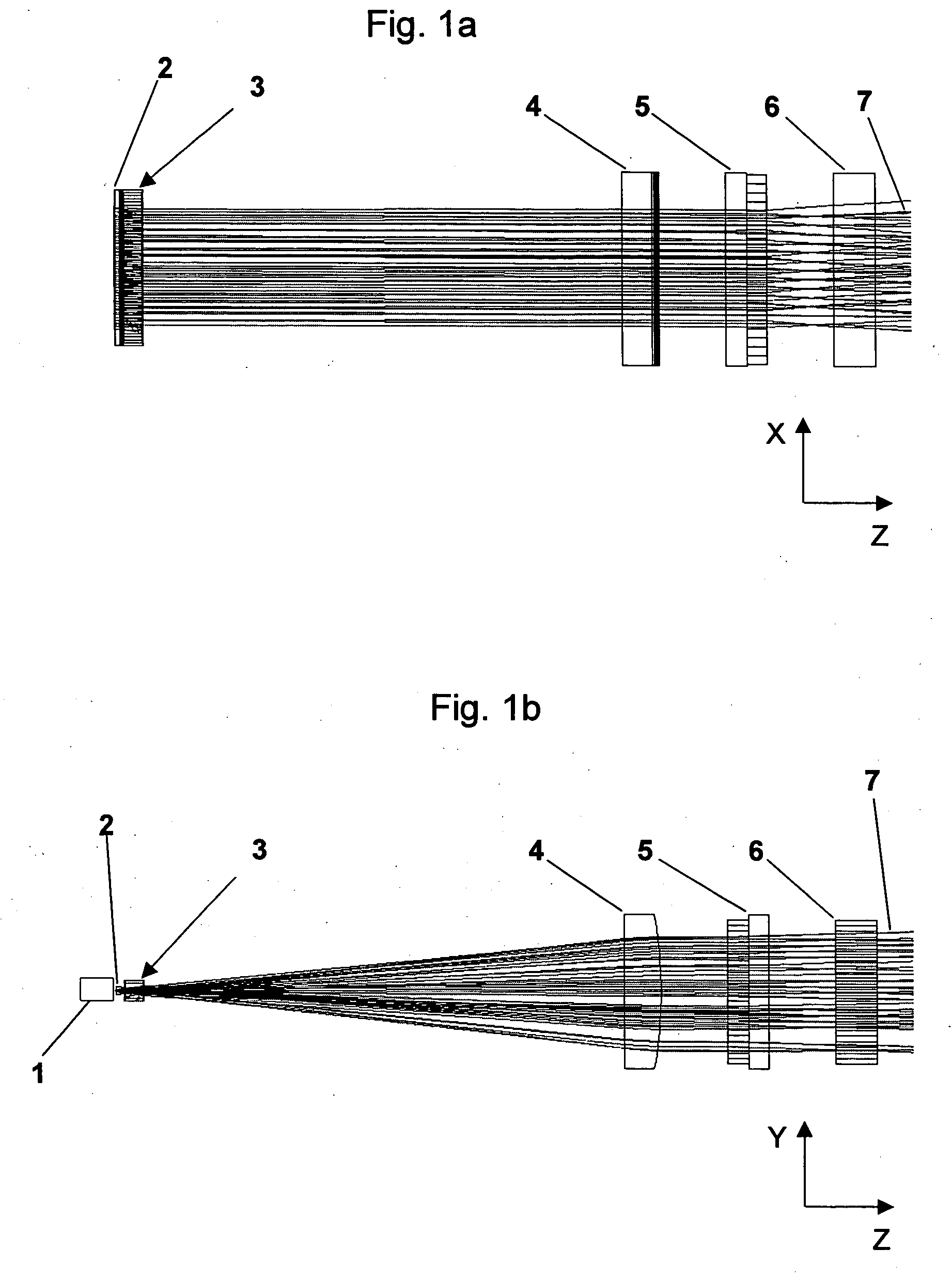
[0022] Cartesian coordinate systems have been drawn in the figures for the sake of better clarity.

[0023] As is to be seen from FIG. 1a and FIG. 1b, an apparatus according to the invention includes a semiconductor laser bar 1 that is designed, in particular, as a so-called QCW bar. Like other semiconductor laser bars, a QCW bar also has a number of emitters arranged next to one another and spaced apart from one another in the X-direction. However, in the case of QCW bars, the spacing between the individual emitters is substantially smaller than the extent of the emitters in the X-direction.

[0024] Sixty emitters, for example, are arranged next to one another and at a spacing from one another in the X-direction, the so-called slow-axis direction, in the case of typical QCW bars. The size of the emitting surfaces of the emitters can in this case be approximately 1 μm in the Y-direction, the so-called fast-axis direction, and approximately 150 μm in the X-direction. Here, the spacing b...


PUM


Abstract

Apparatus for illuminating a surface, having at least one semiconductor laser bar with a plurality of emitters in the case of which the spacing of the individual emitters from one another is smaller than the extent of the emitters in the first direction (X), beam transforming means for transforming the laser light emerging from the emitters that are designed in such a way that they can exchange the divergence of the laser light with regard to the first direction (X) with the divergence with regard to the second direction (Y), the beam transforming means having such a spacing from the laser diode bar that at least the laser light from two directly adjacent emitters overlaps with one another upon impinging on the beam transforming means in the first direction (X).

Description

BACKGROUND OF THE INVENTION [0001] The present invention relates to an apparatus for illuminating a surface, having at least one semiconductor laser bar with a plurality of emitters that are arranged in a first direction next to one another and at a spacing from one another, the spacing of the individual emitters from one another being smaller than the extent of the emitters in the first direction, and the divergence of the laser light emerging from the individual emitters being smaller with regard to the first direction than the divergence of laser light with regard to a second direction perpendicular to the first direction, as well as also comprising collimation means for the at least partial collimation of the laser light emerging from the emitters. [0002] Apparatuses of the abovenamed type are sufficiently known. Semiconductor laser bars with a very small spacing between the individual emitters are generally designed as QCW bars that can be operated in a quasi-continuous fashion...

Claims


Application Information

Patent Timeline
Patent Type & Authority Applications(United States)
IPC IPC(8): H01S3/10G02B27/09H01S3/00
CPCG02B27/0966H01S5/4012G02B19/0014G02B19/0057H01S5/4025G02B27/30G02B27/00
Inventor MITRA, THOMASMEINSCHIEN, JENSHILL, WIELAND
Owner LIMO PATENTVERWALTUNG GMBH & CO KG
Why Eureka
Try Eureka