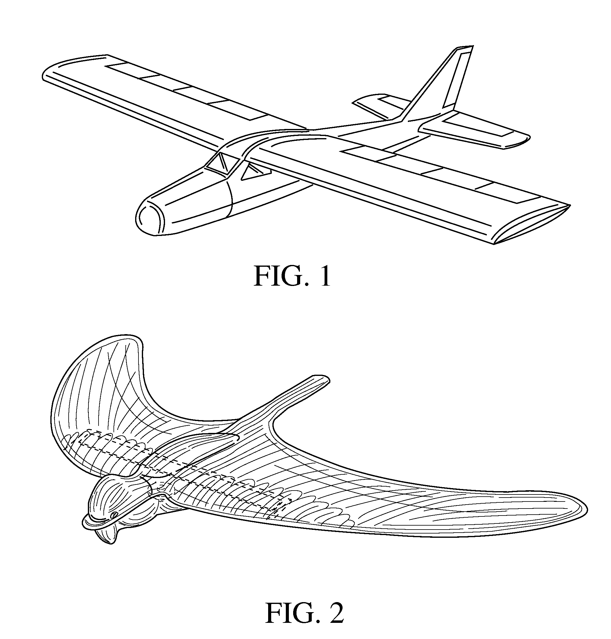
[0004] The present invention provides a toy glider that is low cost, flexible and durable while maintaining desirable flight characteristics. The glider of the present invention is a hollow shell made from a molded thin
film material. The glider can be formed into a variety of different shapes. Typically the glider is formed in the shape of a bird or a plane. The body of the glider comprises a hollow fuselage, a left wing and a right wing extending laterally from the fuselage, a
ballast weight and a stiffener. The interior of the glider is open to the outside
atmosphere and requires no inflation.
[0009] The stiffness and flexibility of the wings is variable from the fuselage to the wingtip. Preferably, the degree of stiffness and flexibility is graduated along the wing. The wings are semi-rigid with a higher degree of rigidity closer to the fuselage while the tips of the wings are flexible. Additionally, the
leading edge of the wing, or a portion thereof, is more rigid than the
trailing edge. The flexibility of the wing improves
flight stability by allowing the glider to adjust to outside forces, such as
wind speed and direction. The stiffness of the wings can be achieved through use of thicker or thinner materials to form the wings, or through the use of a stiffener or additional material in the interior of the glider body at the fuselage / wing area.
[0011] The thin
film material that forms the glider body has a thickness between about 2 mils and about 15 mils. Because less weight results in increased
flight time in typical glider designs, this lightweight construction is advantageous for extended glider flight. More preferably, the thin film material has a thickness between about 3 mils and about 10 mils. A mil is a
unit of length equal to one thousandth (10−3) of an inch (0.0254
millimeter), used, for example, to specify the
diameter of wire or the thickness of materials sold in sheets. In one embodiment of the invention, the thin film forming the glider body has a thickness of approximately 3 mils. In another embodiment, the thin film has a thickness of approximately 10 mils.
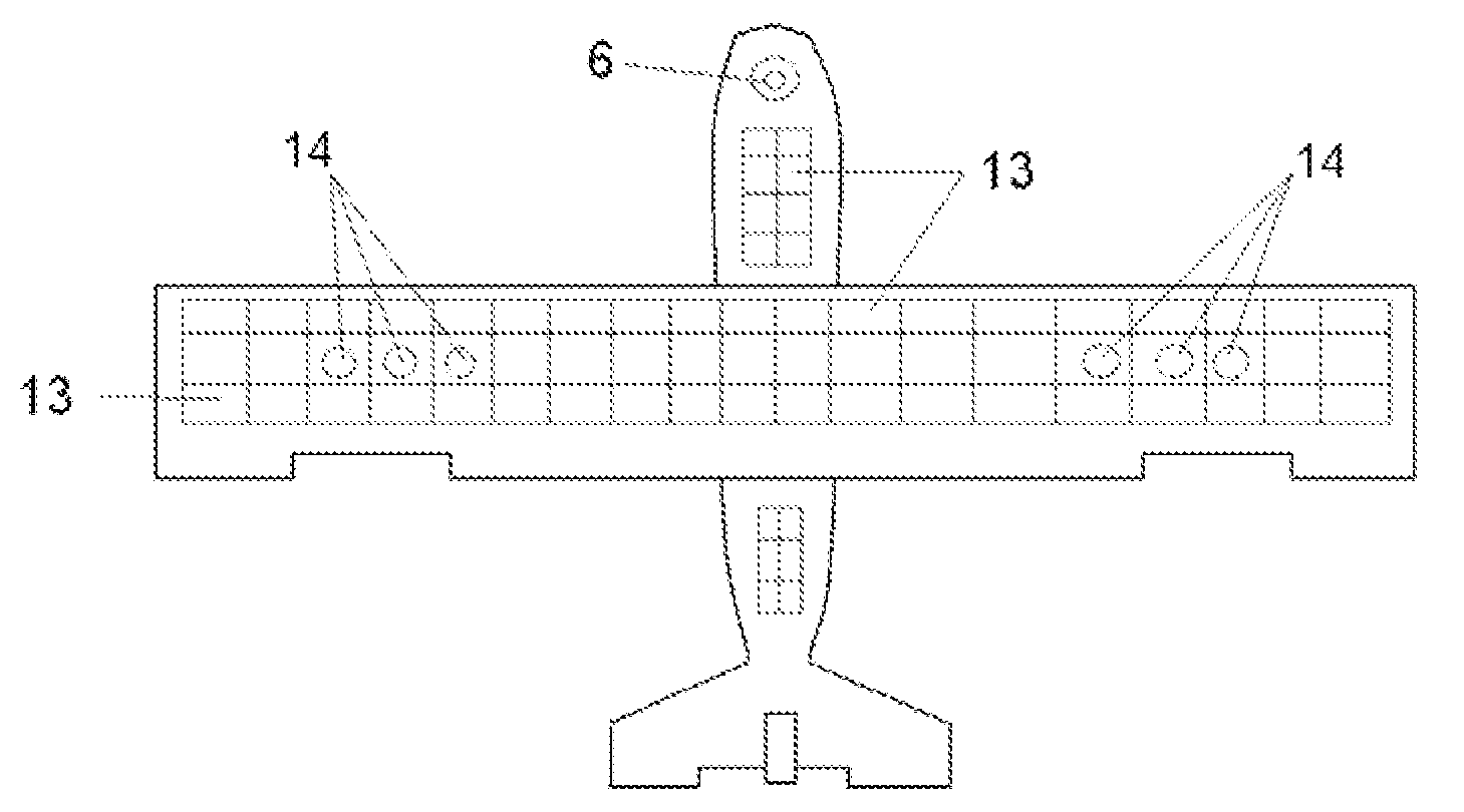
[0013] The glider further comprises a
ballast weight and a stiffener that are encapsulated by the glider body. The ballast weight is any weight or material used to provide the necessary weight and
weight distribution to enhance the flight characteristics of the glider. Materials suitable for use as the ballast weight include, but are not limited to plastic,
metal (such as steel), plaster and
hot melt plastic. The ballast is positioned at or near the front end of the fuselage. The ballast can be welded to the interior of the glider body or attached to an interior skeleton using
hot melt plastic pins. Preferably, the ballast is not set in the front tip of the fuselage so that during a collision between the glider and an object, the front end of the fuselage will be soft, compressible and not damage the object struck by the glider. In one embodiment, the ballast weight is a piece of
metal, such as one or more
metal washers, located in the fuselage between the upper body half and
lower body half.
[0016] Or, the model may be fabricated using injection-molding techniques. The ballast and the wing stiffeners would be attached to recessed areas under the wing and body. The stiffening members and the ballast would be welded or ‘staked’ to the body's undercarriage. The advantages of an
injection molding process include: higher manufacturing volume, less material waste and improved product consistency. Disadvantages include: high initial tooling cost and the final appearance is not pristine. Although hidden by recesses, the ballast and the stiffeners will be visible on the models underside. Specifically, the
injection molding process may be a
blow molding process, which is a technique, used to make plastic bottles.

