Control method and apparatus for discharging condensed water from movable air conditioner

Inactive Publication Date: 2007-01-04
HISENSE HOME APPLIANCES GRP CO LTD
View PDF0 Cites 9 Cited by
  • Summary
  • Abstract
  • Description
  • Claims
  • Application Information

AI Technical Summary

Benefits of technology

[0003] It is an object of the present invention to provide a movable air conditioner capable of discharging condensed water without manual operation by adjusting the air flow over condenser. It is to adjust the condensing temperature bas

Problems solved by technology

Due to a limited volume, frequently, the water tank has to be emptied manually when it is full so that the water tank can be used again; typically, it takes one to two hours to fill up the water tank in a water condensing condition, it is very inconvenient during night time.
This operation extends the fill up time of a water tank, however, the condensed water is generated faster than the exhaustion rate during water condens

Method used


Image

  • Control method and apparatus for discharging condensed water from movable air conditioner
  • Control method and apparatus for discharging condensed water from movable air conditioner
  • Control method and apparatus for discharging condensed water from movable air conditioner

Examples


embodiment 1

Preferred Embodiment 1

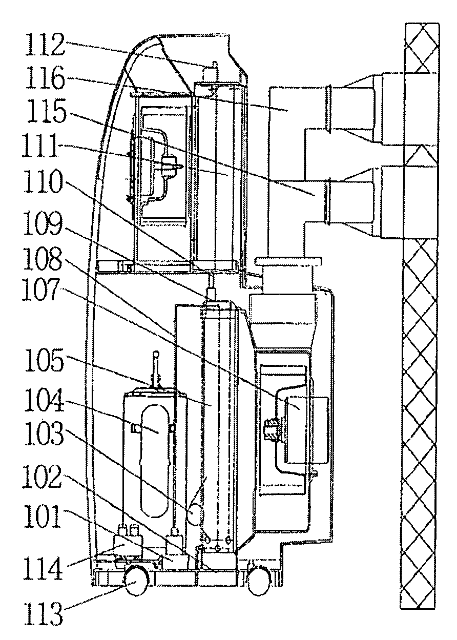
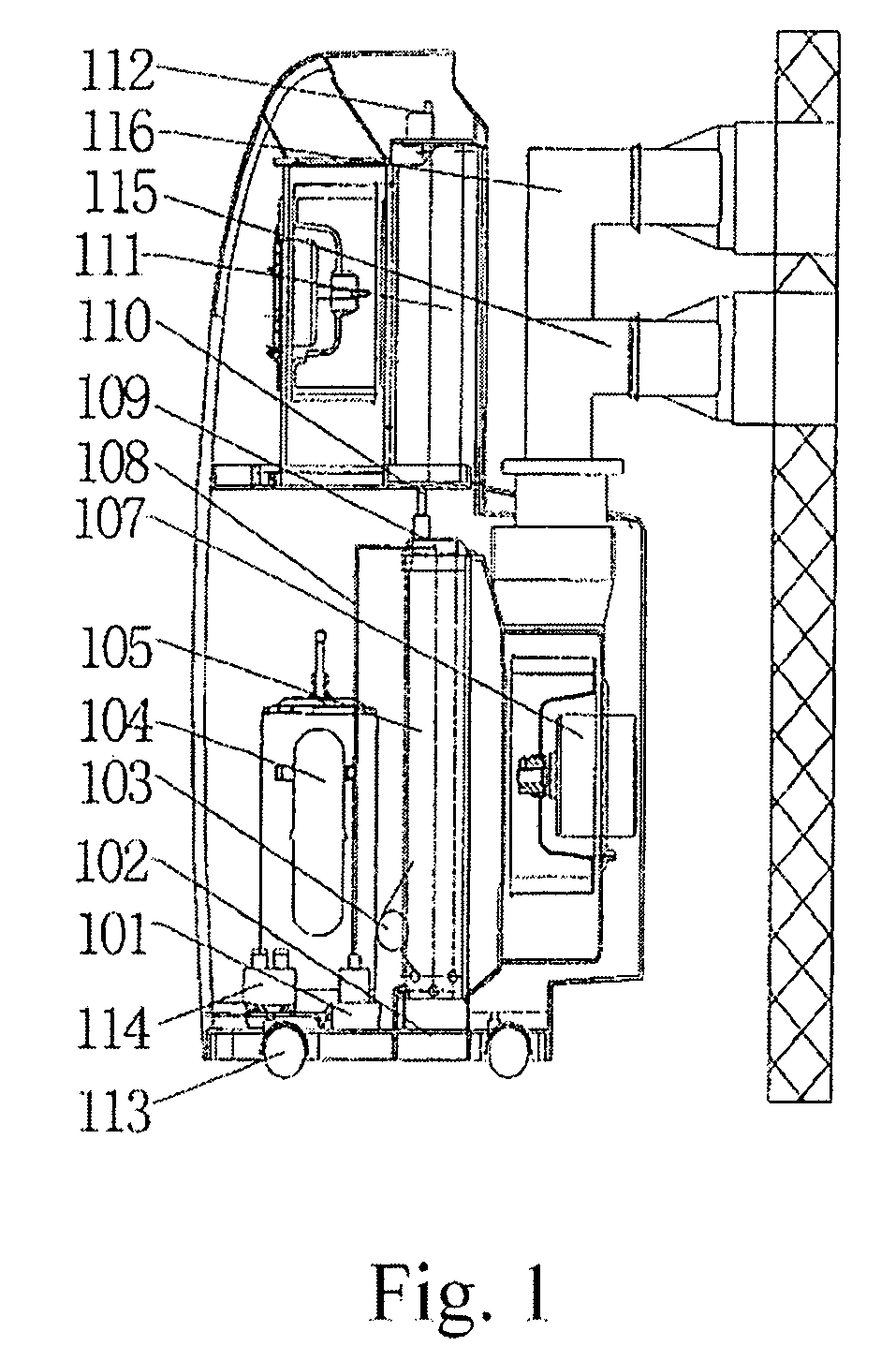
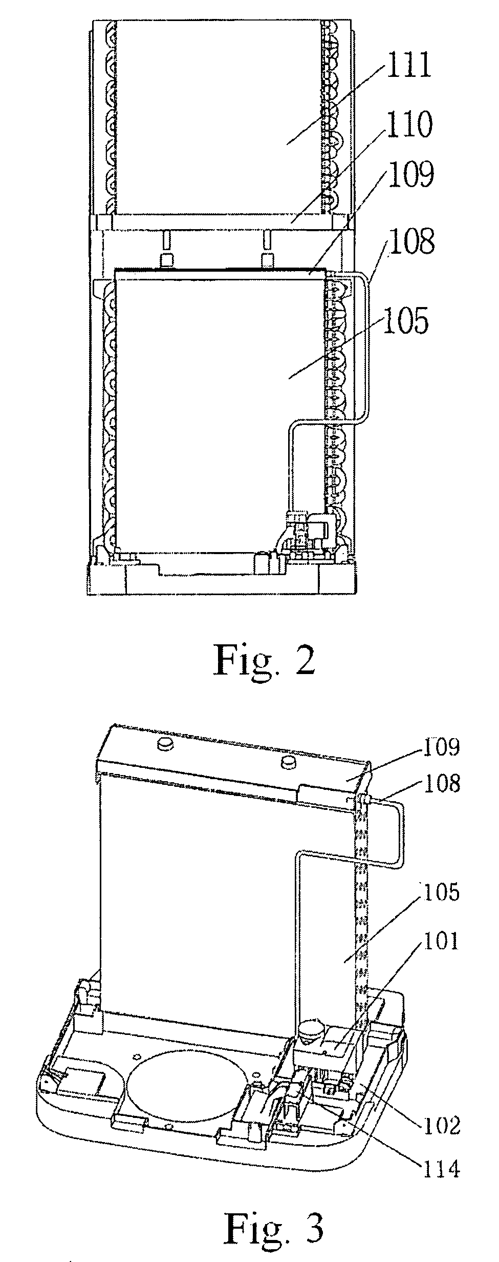
[0026] As shown in FIG. 1, the present invention is related to a duo wind pipe movable air conditioner with foot wheels 113; a condenser 105 and an evaporator 111 of the movable air conditioner respectively employ an independent fan motor, which is controlled by an electronic control system 112. A compressor 114, the condenser 105, a throttle member 103, and the evaporator 111 connected in order make up the cooling system of the movable air conditioner, supplying chilled air for the system. An electronic control system 112 is an electrical system, which provides safe, efficient, and economical control. A spray container 109, a middle separation board 110, a water tank 102, a pump 101 that pumps water to the condenser 105, a water level regulator 114, and an drainage pipe 108 make up the condensed water spray system.

[0027] The movable air conditioner extracts outdoor air into the condenser 105 by a blast pipe 116, the air is then discharged outdoor by an exhaus...

embodiment 2

Preferred Embodiment 2

[0029] As shown in FIG. 5, the cooling circulation mechanism is comprised of a compressor 202, a condenser 208, a throttle member 201, and an evaporator 214 to provide cooling for the system, the electronic control system 206 is an electrical system, which operates safely, efficiently, and economically for the movable air conditioner.

[0030] The movable air conditioner condenser 208 and evaporator 214 share a common motor and fan 207, the indoor air after being extracted into the movable air conditioner will be distributed by the exhaust valve 209 and respectively enters a condenser duct 210 and an evaporator duct 212 separated by a partition 218; the indoor air entering into the evaporator duct 212 exchanges heat with the evaporator 214 and is discharged indoor by an exhaust outlet 215 for cooling afterwards, the indoor air entering into the condenser duct 210 exchanges heat with the condenser 208 and is discharged outdoor by the exhaust pipe 213 afterwards.

[...


PUM


Abstract

A control method for discharging condensed water from a movable air conditioner is provided. No manual operation is necessary to empty the condensed water container. When the condensed water level is higher than a predetermined water level, the conditioner enters into a strong drainage mode operation. Condensing temperature increases and a pump for spraying is activated. The evaporating and draining speed increase as well. Evaporated condensed water will be discharged outdoor as air discharged from the condenser by the exhaust pipe; the rest of the condensed water will flow downward from the condenser to a water tank. When condensed water level bellows the predetermined water level, the conditioner exits the strong drainage mode and enters into a normal operation mode. The heat exchange efficiency of the condenser is also improved by utilizing the condensed water spray circulation system.

Description

FIELD OF THE INVENTION [0001] The present invention relates to an air conditioner, particularly relates to a movable air conditioner that is capable of discharging condensed water without manual operation. The present invention still relates to a control method for discharging condensed water from a movable air conditioner. BACKGROUND OF THE INVENTION [0002] During the cooling operation of a movable air conditioner, if the temperature of the evaporator surface is lower than the room temperature, humidity will be condensed out of the evaporator. There are two major methods used for discharging condensed water from a movable air conditioner in the market: one is directly collecting the condensed water into a water tank. Due to a limited volume, frequently, the water tank has to be emptied manually when it is full so that the water tank can be used again; typically, it takes one to two hours to fill up the water tank in a water condensing condition, it is very inconvenient during night...

Claims


Application Information

Patent Timeline
IPC IPC(8): F25D21/00F25D23/06F25D19/00F24F1/04F24F13/22
CPCF24F13/222F24F2221/125F24F2013/225F24F2011/0054F24F2140/30
Inventor HUANG, XIAOFENGLI, ZHIJUNTAN, YUHUITANG, WEICHEN, SHAO'ANGAO, ZUYU
Owner HISENSE HOME APPLIANCES GRP CO LTD
Why Eureka
Try Eureka