Moving body

a moving body and body technology, applied in the field of moving bodies, can solve the problems of releasing water to swash on a pedestrian, troublesome subsequent and nearby vehicles, etc., and achieve the effect of restrainting the splashing of discharged water

Inactive Publication Date: 2007-01-04
TOYOTA JIDOSHA KK
View PDF11 Cites 29 Cited by
  • Summary
  • Abstract
  • Description
  • Claims
  • Application Information

AI Technical Summary

Benefits of technology

[0050] The fifth moving body of the invention has the water tank located in the exhaust system and the drain formed in the front portion of the moving body to discharge the water from the water tank. The fifth moving body of the invention may have insufficient effects of restraining the water discharge under the condition of the high-speed motion of the moving body. As mentioned above, the presence of the front-facing opening restricts water discharge under acceleration of the moving body, while facilitating water discharge under deceleration of the moving body. During a general run, the moving body often repeats acceleration and deceleration and does not continue running at a fixed cruising speed. The arrangement of facilitating the water discharge under deceleration and restraining the water discharge under acceleration thus reduces scatter of the discharged water during a run of the moving body to the level that does not interfere with smooth driving of subsequent and nearby moving bodies. Here a typical example of the moving body is a vehicle.
[0051] In the fifth moving body of the invention, the water tank and the drain may be located inside the moving body to discharge water out of the moving body through an exhaust pipe. In one preferable embodiment of the fifth moving body of the invention, the drain has an opening at a position and orientation to make a ram pressure produced by motion of the moving body act in a direction of restricting discharge of the water. In one preferable structure of this embodiment, the water tank is attached to the outside of the moving body. This structure ensures application of the ram pressure onto the drain. In another preferable structure of this embodiment, the water tank is located inside the moving body, whereas the drain is formed outside the moving body. Application of the ram pressure onto the drain restricts the water discharge under the condition of the high-speed motion of the moving body and thereby effectively restrains splash of the discharged water.

Problems solved by technology

Even when the water is released in such a manner that does not wet wheels to avoid a potential skid, the released water may cause some troubles on subsequent and nearby vehicles.
The release of the water in a lateral direction, however, may cause the released water to swash on a pedestrian on the road shoulder or a nearby building.

Method used


Image

  • Moving body
  • Moving body
  • Moving body

Examples


first embodiment

A. First Embodiment

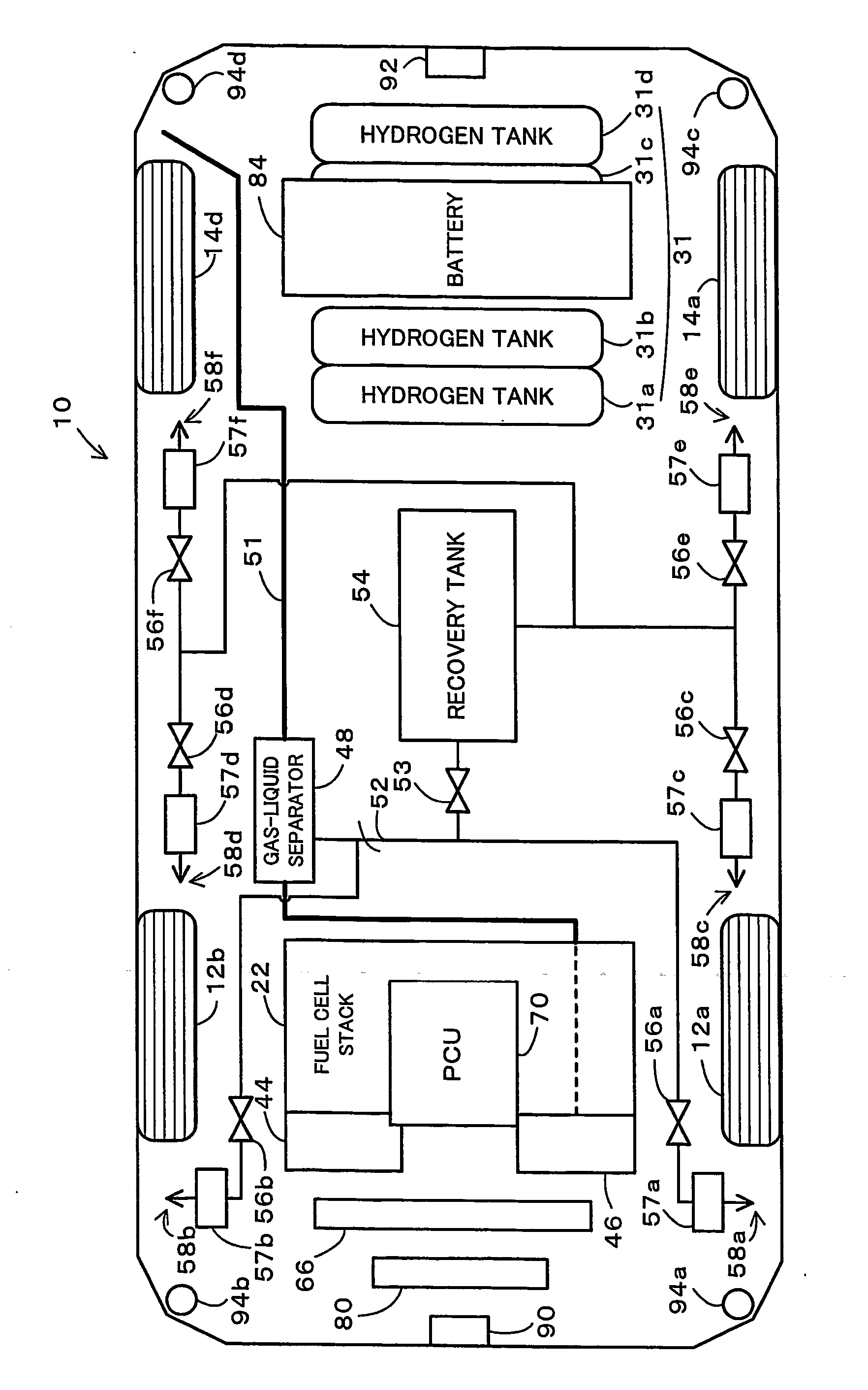
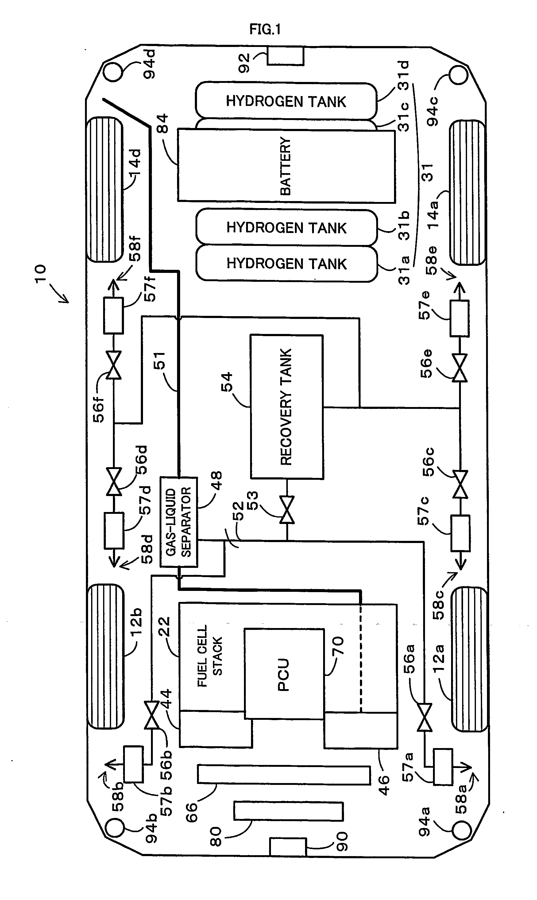
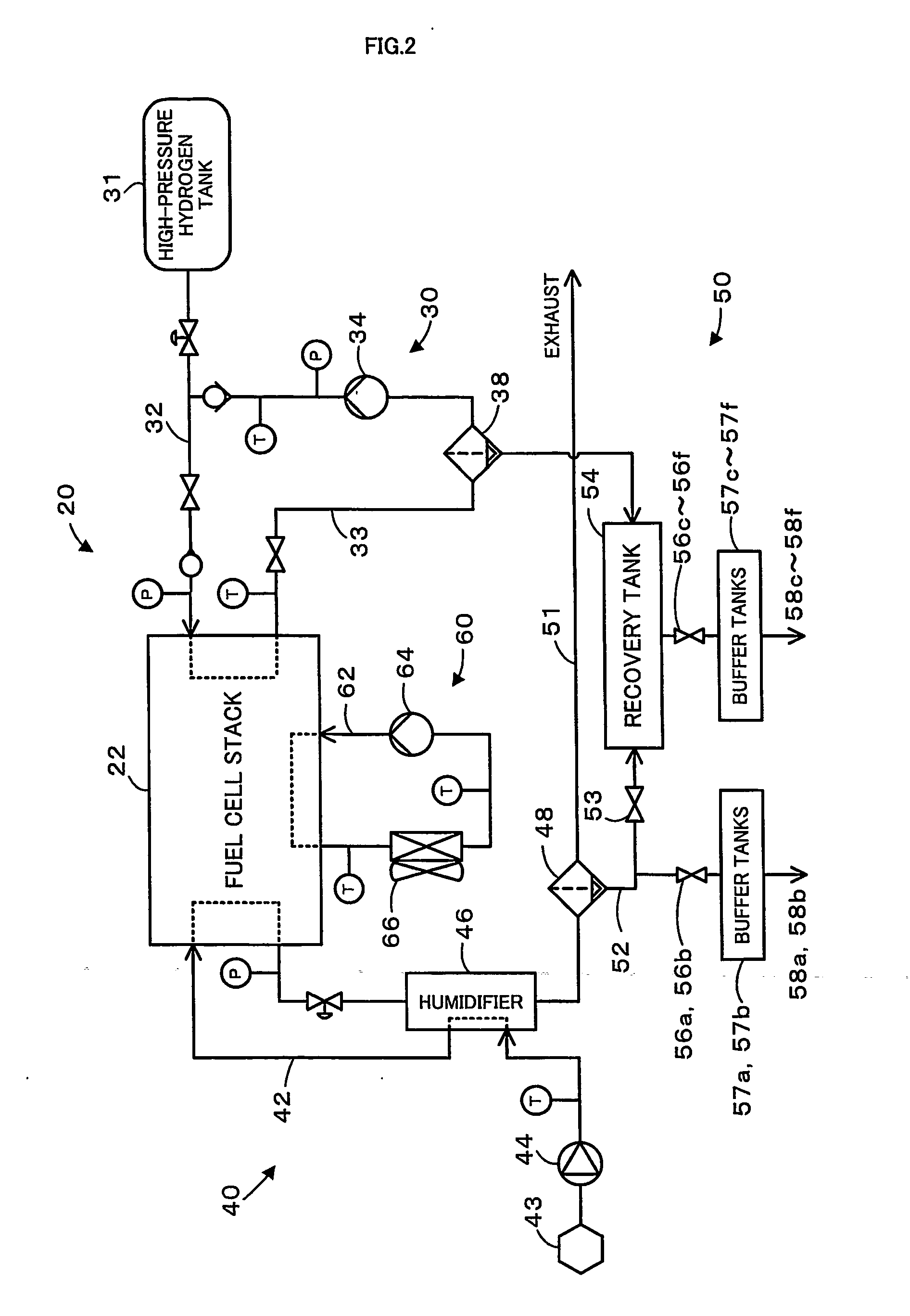
[0056]FIG. 1 is a plan view showing a plane layout of devices mounted on a fuel cell vehicle 10 as a moving body of a first embodiment of the invention. FIG. 2 is a system diagram schematically showing the configuration of a fuel cell system 20 mounted on the fuel cell vehicle 10 of the first embodiment. For simplicity of explanation, the description first regards the configuration of the fuel cell system 20 with reference to the system diagram of FIG. 2 and then the layout of the respective devices included in the fuel cell system 20 with reference to FIG. 1

[0057] The fuel cell system 20 mounted on the fuel cell vehicle 10 of the first embodiment includes a fuel cell stack 22 or a stack of multiple layers of unit cells, each of which has two electrodes (a fuel electrode and an air electrode) arranged across a polymer electrolyte membrane. The fuel cell system 20 also includes a hydrogen supply system 30 that feeds a supply of hydrogen from a high-pressure hydroge...

second embodiment

B. Second Embodiment

[0103] The following describes another fuel cell vehicle 210 as a moving body in a second embodiment of the invention. FIG. 17 is a plan view showing a plane layout of devices mounted on the fuel cell vehicle 210 of the second embodiment. FIG. 18 is a system diagram schematically showing the configuration of a fuel cell system 220 mounted on the fuel cell vehicle 210 of the second embodiment. As shown in FIGS. 17 and 18, the fuel cell vehicle 210 of the second embodiment has the configuration similar to that of the fuel cell vehicle 10 of the first embodiment, except a variable-direction outlet 260 located on a discharge end of the exhaust gas pipe 51 included in the fuel cell system 220. In order to avoid the duplicate explanation, the like constituents in the fuel cell vehicle 210 of the second embodiment to those in the fuel cell vehicle 10 of the first embodiment are expressed by the like numerals and are not specifically described here.

[0104] With reference...

third embodiment

C. Third Embodiment

[0113] The following describes still another fuel cell vehicle 310 as a moving body in a third embodiment of the invention. FIG. 25 is a plan view showing a plane layout of devices mounted on the fuel cell vehicle 310 of the third embodiment. As shown in FIG. 25, the fuel cell vehicle 310 of the third embodiment has the configuration similar to that of the fuel cell vehicle 210 of the second embodiment, except that the direction of the variable-direction outlet 260 located on the discharge end of the exhaust gas pipe 51 is adjusted to be identical with the moving direction of the vehicle. In order to avoid the duplicate explanation, the like constituents in the fuel cell vehicle 310 of the third embodiment to those in the fuel cell vehicle 210 of the second embodiment are expressed by the like numerals and are not specifically described here.

[0114] In the fuel cell vehicle 310 of the third embodiment, the electronic control unit 271 executes a release direction c...


PUM

PropertyMeasurementUnit
timeaaaaaaaaaa
speedaaaaaaaaaa
speedaaaaaaaaaa

Abstract

Water contained in exhaust gas discharged from a fuel cell stack 22 is separated by a gas-liquid separator 48 and is accumulated in a recovery tank 54. The procedure of the invention sets a release amount of water and selects one or multiple positions for water release, based on the driving conditions including the vehicle speed and the acceleration, the turning state, activation or non-activation of skid reduction control, the distance from any object detected by clearance sonars 94a through 94d, a distance from a subsequent vehicle measured by an extremely high frequency radar 92, and the presence of raindrops detected by a raindrop detection sensor, and releases the water accumulated in the recovery tank 54 from water outlets at the selected one or multiple positions among water outlets 58a through 58f at multiple different locations. This arrangement ensures adequate release of the water produced by the fuel cell stack 22 to the atmosphere.

Description

TECHNICAL FIELD [0001] The present invention relates to a moving body. Specifically, the invention relates to a moving body with fuel cells that are mounted thereon as a power source and generate electric power with production of water as a by-product BACKGROUND ART [0002] One example of proposed moving bodies is a motorcycle that releases water produced by fuel sells on the side of the vehicle (see, for example, Japanese Patent Laid-Open Gazette No. 2001-313056). Release of the water produced by the fuel cells on the side of the vehicle prevents potential troubles caused by splash of the water on wheels, for example, a skid of the wheels. DISCLOSURE OF THE INVENTION [0003] As described above, the vehicle with fuel cells mounted thereon requires release of water, which is produced by the fuel cells, out of the vehicle during a run. Even when the water is released in such a manner that does not wet wheels to avoid a potential skid, the released water may cause some troubles on subseq...

Claims


Application Information

Patent Timeline
Patent Type & Authority Applications(United States)
IPC IPC(8): B60L8/00H01M2/02B60K1/04B60K1/00B60K8/00B60K15/07B60L11/18H01M8/00H01M8/06
CPCB60K1/00B60K15/07B60K2001/005H01M8/04179Y02E60/50H01M8/04059H01M8/04156Y02T10/7072H01M8/04H01M8/02
Inventor YOSHIDA, NAOHIROKONDO, TOSHIYUKIHIBINO, MASAHIKOYUMITA, OSAMUFUNAYAMA, YOSHIHIRO
Owner TOYOTA JIDOSHA KK
Why Eureka
Try Eureka