

Electrochemical device
a technology of electrochemical devices and electrodes, applied in the direction of electrical devices, metal-working devices, cell structural combinations, etc., can solve the problems of increasing the negative effect of volume energy density, and achieve the effects of improving reliability, reducing the amount of energy consumed, and saving spa
- Summary
- Abstract
- Description
- Claims
- Application Information
AI Technical Summary
Benefits of technology
Problems solved by technology
Method used
Image

Examples
first embodiment
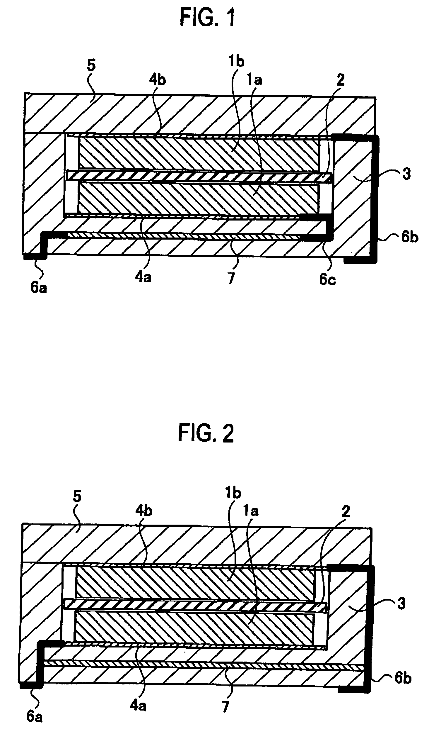
[0022] In a first embodiment, an electric double layer capacitor provided with a fame body having concave shape and a sealing plate will be described as an example of an electrochemical device.
[0023] As shown in FIG. 1, the electric double layer capacitor includes a pair of polarizable electrodes 1a and 1b, a separator 2 interposed between the pair of polarizable electrodes 1a and 1b, and an electrolytic solution to be impregnated into the pair of polarizable electrodes 1a and 1b and the separator 2 In addition, a container for housing the pair of polarizable electrodes 1a and 1b and the electrolytic solution includes a frame body 3 having concave shape and a sealing plate 5 for sealing an opening of the frame body 3.
[0024] A collector 4a is disposed on an inner bottom surface of the frame body 3, and a collector 4b is disposed on an inner surface of the sealing plate 5 at the side of the polarizable electrode 1b. Note that the polarizable electrode 1a is joined to the collector 4...
second embodiment
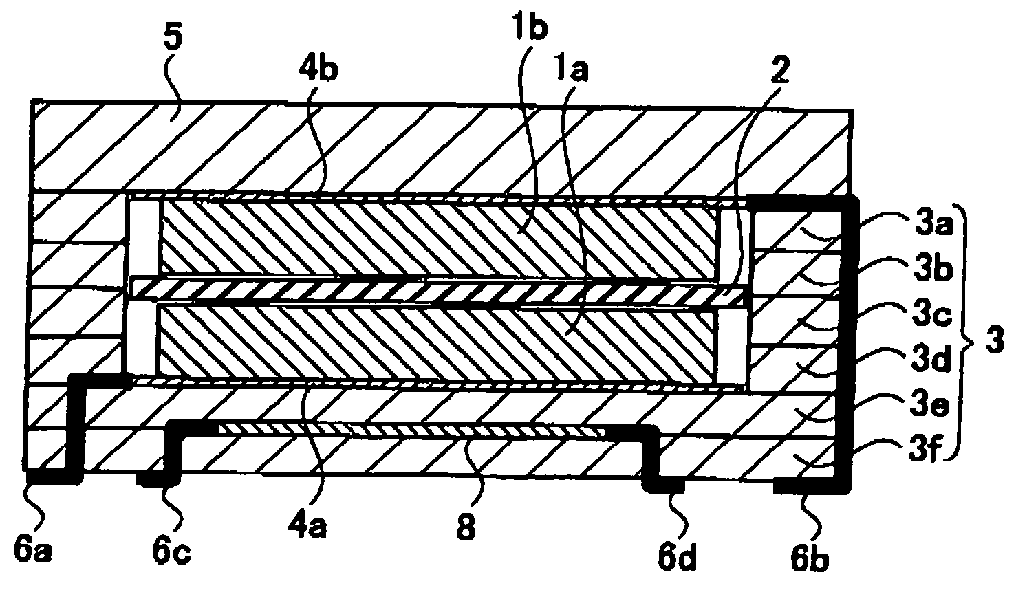
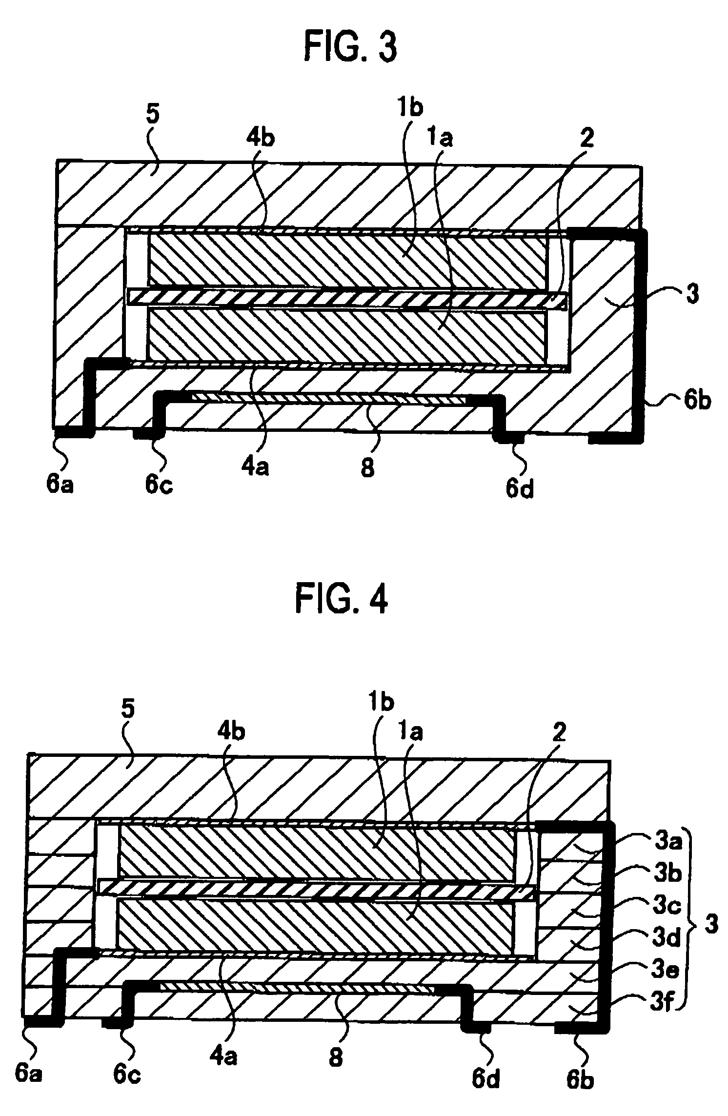
[0037] In a second embodiment, an electric double layer capacitor provided with a frame body having concave shape and a sealing plate will be described as an example of the electrochemical device.
[0038] As shown in FIG. 4, the electric double layer capacitor includes a pair of polarizable electrodes 1a and 1b, a separator 2 interposed between the pair of polarizable electrodes 1a and 1b, and an electrolytic solution to be impregnated into the pair of polarizable electrodes 1a and 1b and the separator 2. In addition, a container for housing the pair of polarizable electrodes 1a and 1b and the electrolytic solution is configured of a frame body 3 having concave shape and a sealing plate 5 for sealing an opening of the frame body 3.
[0039] A collector 4a is disposed on an inner bottom surface of the frame body 3, and a collector 4b is disposed on an inner surface of the sealing plate 5 on the side of the polarizable electrode 1b. Note that the polarizable electrode 1a is joined to the...
example 1
[0055] In Example 1, the polarizable electrodes 1a and 1b are fabricated, and concurrently, the electrolytic solution is prepared to produce an electric double layer capacitor as shown in FIG. 1.
[Fabrication of Polarizable Electrodes]
[0056] The polarizable electrodes 1a and 1b in a square shape having a side of 3.8 mm and a thickness of 0.5 mm are formed by adding 5 wt % of acetylene black and 5 wt % of polytetrafluoroethylene (PTFE) to activated carbon powder having a specific surface area of 2000 m2 / g, and by kneading these materials.
[Preparation of Electrolytic Solution]
[0057] An electrolytic solution is prepared by dissolving (C2H5)4NBF4, which is a solute, into a propylene carbonate as a solvent to achieve a concentration of 1 mol / l.
[Production of Electric Double Layer Capacitor Cell]
[0058] The two polarizable electrodes 1a and 1b fabricated as described above are disposed so as to face each other while interposing the separator 2 made of glass fibers therebetween. This g...
PUM
 Abstract
Description
Claims
Application Information