Layered shell vacuum balloons

a vacuum balloon and layered shell technology, applied in the field of lighter-than-air structures, can solve the problems of loss of stability, simple evaluation of compressive stress in section 11/b>, loss of stability, etc., and achieve the effect of enhancing the resistance to buckling

Inactive Publication Date: 2007-01-04
FLORIDA STATE UNIV RES FOUND INC
View PDF9 Cites 13 Cited by
  • Summary
  • Abstract
  • Description
  • Claims
  • Application Information

AI Technical Summary

Benefits of technology

[0022] The present invention comprises a new type of vacuum balloon. A layered wall structure is used, including a relatively thick cellular section sandwiched between and bonded to two relatively thin layers. Different materials are selected for the thick section versus the thin layers (In some instances they may be made from the same materials, but processed in a different way). The layered wall design is used to form a thin-walled sphere having greatly enhanced resistance to buckling. Using this approach it is possible to create a rigid vacuum balloon, having positive buoyancy, which is also strong enough to withstand atmospheric pressure.

Problems solved by technology

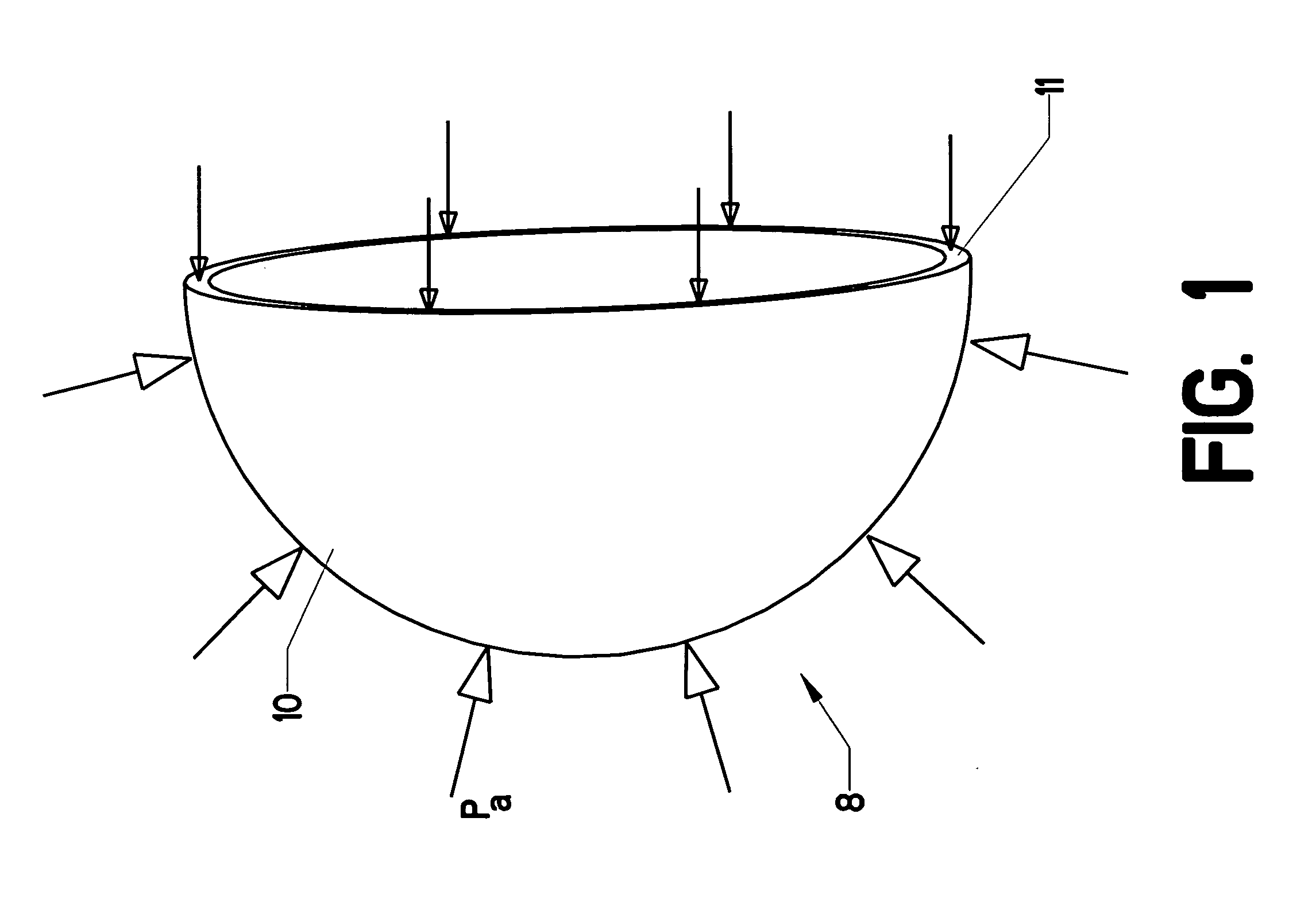
However, those skilled in the art will realize that a simple evaluation of the compressive stress in analyzed section 11 is insufficient to predict the resistance of the thin shell to compression when evacuated.
Thin shells typically fail by buckling (loss of stability).
Thus, even diamond is not nearly strong enough to form a vacuum balloon using a homogenous wall structure.
No known material can be used to create a vacuum balloon made from a homogenous wall structure.
However, upon closer reading, the '745 disclosure has no information regarding how the proposed structure could actually achieve positive buoyancy.

Method used


Image

  • Layered shell vacuum balloons
  • Layered shell vacuum balloons
  • Layered shell vacuum balloons

Examples


Embodiment Construction

[0058]FIG. 3 shows a new type of wall section used in the present invention. Layered shell 12 is formed in the shape of a thin-walled hollow sphere. FIG. 3 shows a small portion of the wall. Inner layer 14 faces the sphere's hollow interior. Outer layer 18 covers the outside of the sphere. Sandwiched between inner layer 14 and outer layer 18 is core layer 16. These three layers are bonded together using adhesives or other known processes. Those skilled in the art will know that adhesives have been successfully used for many years in the creation of thin-walled honeycomb structures.

[0059] Core layer 16 is made of a material having the following properties: [0060] 1. low density; [0061] 2. relatively high compressive strength in the transverse (radial) direction; [0062] 3. relatively high out-of-plane shear strength; [0063] 4. relatively high compressive modulus of elasticity in the transverse (radial) direction; and [0064] 5. relatively high out-of-plane shear modulus.

[0065] One su...


PUM


Abstract

A new type of vacuum balloon. A layered wall structure is used, including a relatively thick honeycombed section sandwiched between and bonded to two relatively thin layers. This layered wall design is used to form a thin-walled sphere having greatly enhanced resistance to buckling. Using this approach it is possible, with existing materials, to create a rigid vacuum balloon having positive buoyancy.

Description

MICROFICHE APPENDIX [0001] Not Applicable BACKGROUND OF THE INVENTION [0002] 1. Field of the Invention [0003] This invention relates to the field of lighter-than-air structures. More specifically, the invention comprises a rigid “balloon” having a layered shell comprised of specified materials and dimensions. The selection of appropriate materials and dimensions allows the balloon to simultaneously achieve sufficient compressive strength, buckling stability, and positive buoyancy. [0004] 2. Description of the Related Art [0005] The concept of using a rigid evacuated shell as a lifting device is several centuries old. Lift is created by evacuating a weight of air which is greater than the weight of the structure of the shell itself, thereby creating a “vacuum balloon.” Of course, the structure must be able to resist the compressive forces exerted by the surrounding atmosphere. A simple analysis of these forces illustrates why the concept of a vacuum balloon has not been realized in f...

Claims


Application Information

Patent Timeline
Patent Type & Authority Applications(United States)
IPC IPC(8): B64B1/02
CPCB64B1/06B64B1/58B64B1/16B64B1/40
Inventor AKHMETELI, ANDREY M.GAVRILIN, ANDREY V.
Owner FLORIDA STATE UNIV RES FOUND INC
Why Eureka
Try Eureka