Ceramic lamp having molybdenum-rhenium end cap and systems and methods therewith

a technology of molybdenum rhenium end cap and ceramic lamp, which is applied in the manufacture of electrode systems, electric discharge tubes/lamps, cold cathode manufacturing, etc., can solve the problems of thermal stress cracks during lamp operation, significant challenges in the process of joining different materials in high-temperature lamps, and inability to chemically resist halide species

Inactive Publication Date: 2007-01-04
GENERAL ELECTRIC CO
View PDF18 Cites 11 Cited by
  • Summary
  • Abstract
  • Description
  • Claims
  • Application Information

AI Technical Summary

Benefits of technology

[0005] Embodiments of the present invention provide a ceramic lamp with a molybdenum-rhenium end structure capable of improved performance, such as light output, color stability, reliability, and life, over the existing traditional technologies. Certain embodiments of the lamp have an arc envelope and a molybdenum-rhenium end structure bonded to the arc envelope with the end structure overlapping an outer-perimeter of the arc envelope. Another embodiment is a system, which has an end structure comprising molybdenum-rhenium, a ceramic arc envelope coupled to the end structure, a dosing tube extending through the end structure and a dosing material disposed within the arc envelope. In another embodiment, the present technique includes the method for making a lamp with an arc envelope bonded to a molybdenum-rhenium end structure, with a dosing material disposed within the arc envelope. In a further embodiment, the present technique includes a method for operating a lamp with an arc envelope bonded to a molybdenum-rhenium end structure. In a still further embodiment is a method of making a molybdenum rhenium end structure.

Problems solved by technology

Because of operational limitations, various parts of these lamps are made of different types of materials.
The process of joining different materials in high-temperature lamps creates significant challenges.
Specifically, the different thermal coefficients of expansion of these joined materials can lead to thermal stresses and cracks during operation of the lamp.
Certain end-cap materials used to provide favorable and reliable stress distribution in the ceramic at the end of the ceramic lamp, unfortunately, are not chemically resistant to halide species that may be used in the lamps, especially at elevated temperatures.
Unfortunately, this requirement of a dry box environment with a furnace disposed within the box severely limits production efficiency of the lamps.
Dry box processing makes it difficult to seal lamps with such high pressure fills.

Method used


Image

  • Ceramic lamp having molybdenum-rhenium end cap and systems and methods therewith
  • Ceramic lamp having molybdenum-rhenium end cap and systems and methods therewith
  • Ceramic lamp having molybdenum-rhenium end cap and systems and methods therewith

Examples


Embodiment Construction

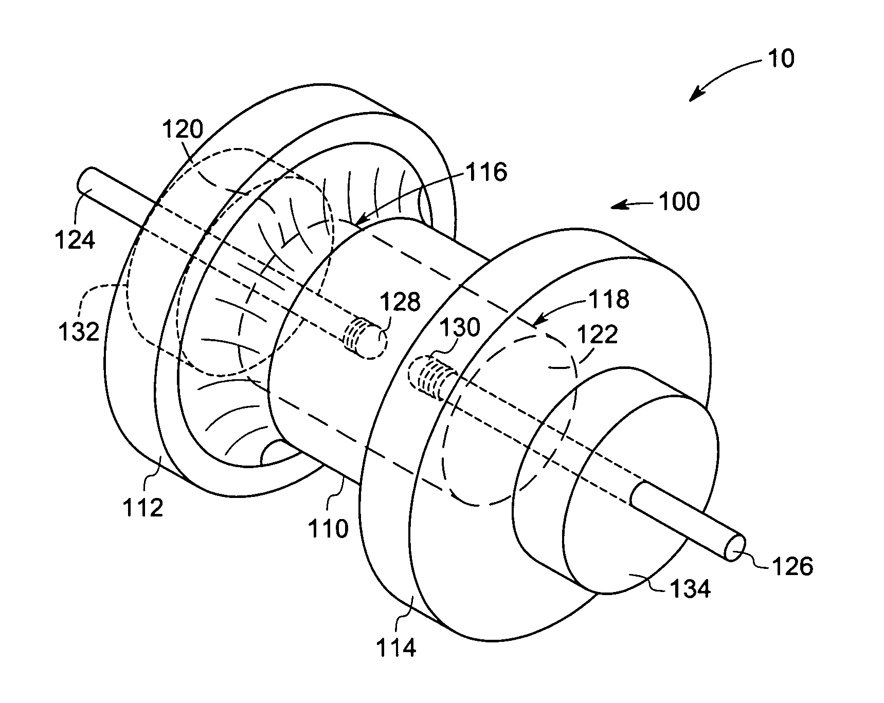
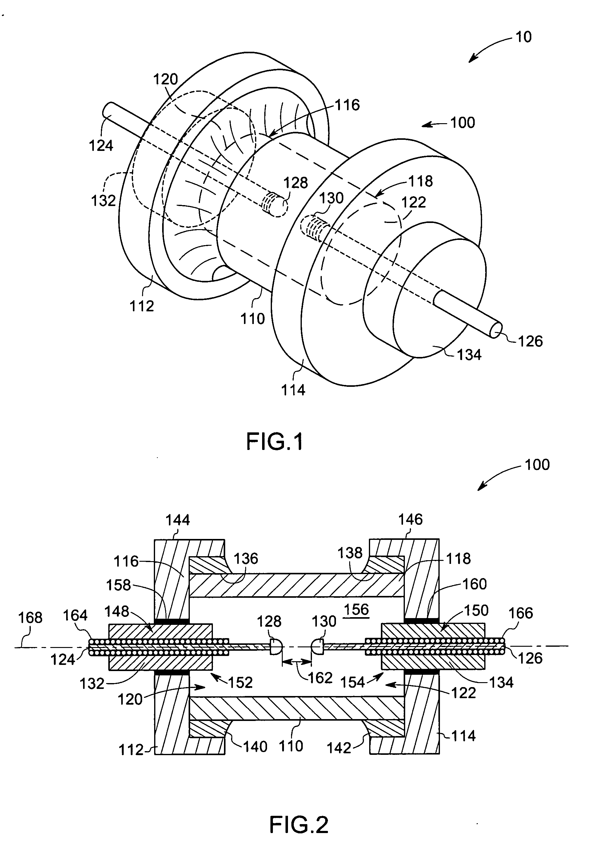
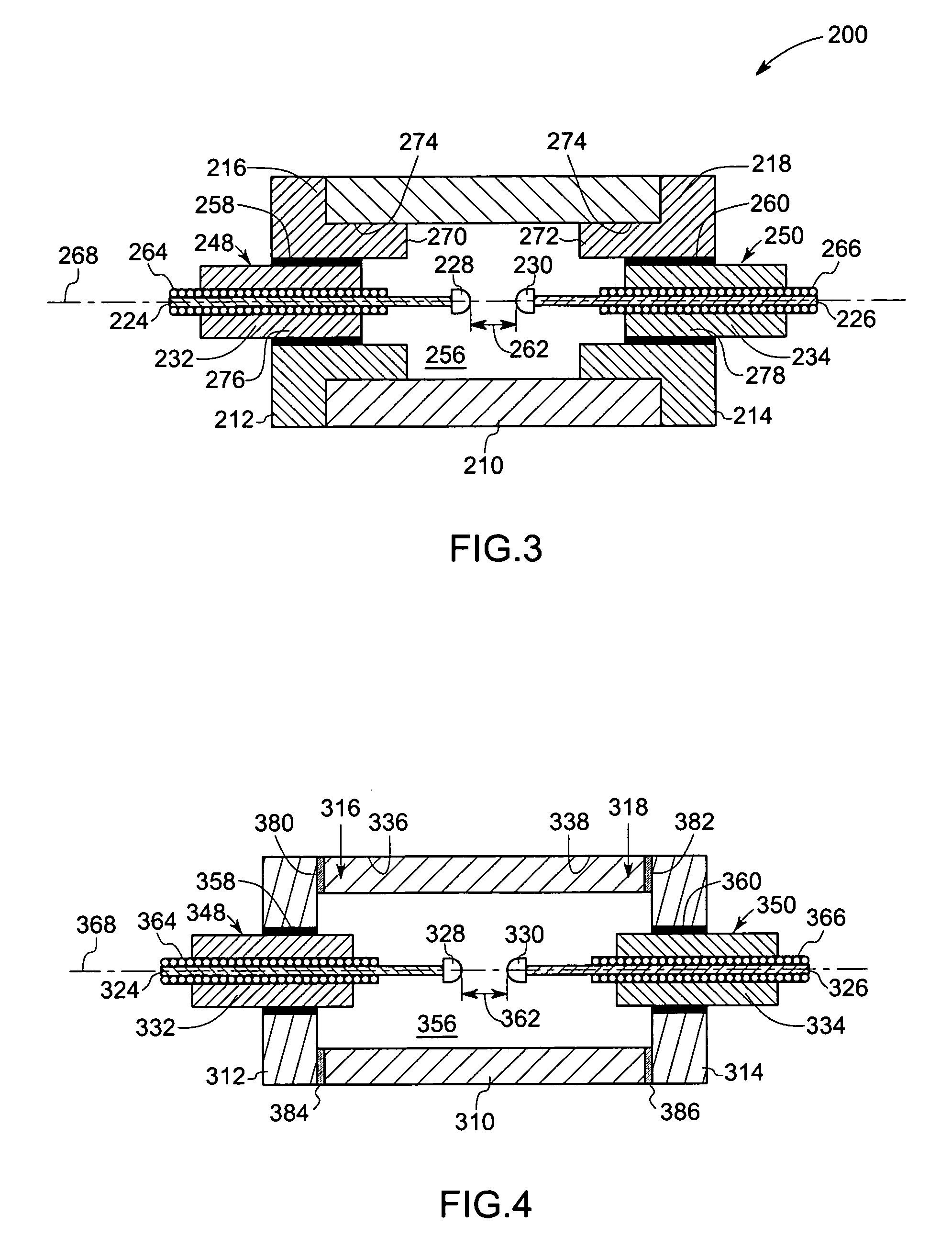
[0017] Embodiments of the present technique provide unique ceramic arc lamps comprising an arc envelope having a molybdenum-rhenium end structure, which improves performance and mechanical stability of the lamp. The metallic end structure design also desirably provides better thermal stress management during lamp start-up and better thermal management of cold spot temperature. In certain embodiments, these lamps include dosing tubes to facilitate dosing without the use of a hot furnace and dry box environment. In some embodiments, the concentration of rhenium in the molybdenum rhenium alloy is in a range from about 5% to about 60% by weight. In certain other embodiments, the rhenium concentration is in a range from about 10% to about 55% by weight. In some other embodiments, the rhenium concentration is in a range from about 38% to about 48%. The unique features introduced above are described in detail below with reference to figures of several exemplary embodiments of the present t...


PUM


Abstract

A lamp comprising an arc envelope and a molybdenum-rhenium end structure coupled to the arc envelope.

Description

BACKGROUND [0001] The present technique relates generally to the field of lighting systems and, more particularly, to high intensity discharge lamps. [0002] High intensity discharge lamps are often formed from a ceramic tubular body or arc tube that is sealed to one or more end caps or end structures. High intensity discharge lamps generally operate at high temperatures and high pressures. Because of operational limitations, various parts of these lamps are made of different types of materials. The process of joining different materials in high-temperature lamps creates significant challenges. Specifically, the different thermal coefficients of expansion of these joined materials can lead to thermal stresses and cracks during operation of the lamp. For example, thermal stresses and cracks can develop at the seal interface between the different components, e.g., arc tube, electrodes, end caps, and so forth. Certain end-cap materials used to provide favorable and reliable stress distr...

Claims


Application Information

Patent Timeline
Patent Type & Authority Applications(United States)
IPC IPC(8): H01J17/18
CPCH01J9/395H01J9/40H01J61/12H01J61/366H01J61/361H01J61/363H01J61/36
Inventor BEWLAY, BERNARD PATRICKKNUDSEN, BRUCE ALANRAHMANE, MOHAMEDBREWER, JAMES ANTHONYVARTULI, JAMES SCOTTCHALMERS, ALAN GEORGE
Owner GENERAL ELECTRIC CO
Why Eureka
Try Eureka