

System and method for locomotive adhesion control
a technology for adhesion control and locomotives, applied in the direction of motor/generator/converter stopper, dynamo-electric converter control, multiple dynamo-motor starters, etc., can solve the problem of reducing or losing the adhesion of wheel-to-rail, excessive slippage of all vehicle wheels, and increased actual slippage or creep. the effect of the optimum creep
- Summary
- Abstract
- Description
- Claims
- Application Information
AI Technical Summary
Benefits of technology
Problems solved by technology
Method used
Image

Examples
Embodiment Construction
[0020] Through the present discussion, it should be noted that the present invention may be utilized with various types of alternating current (AC) induction motor and DC motor powered vehicles such as off-highway vehicles (earth-moving machines), transit cars, and railroad locomotives. By way of example and not limitation, the invention is described herein as it may be applied to a locomotive.
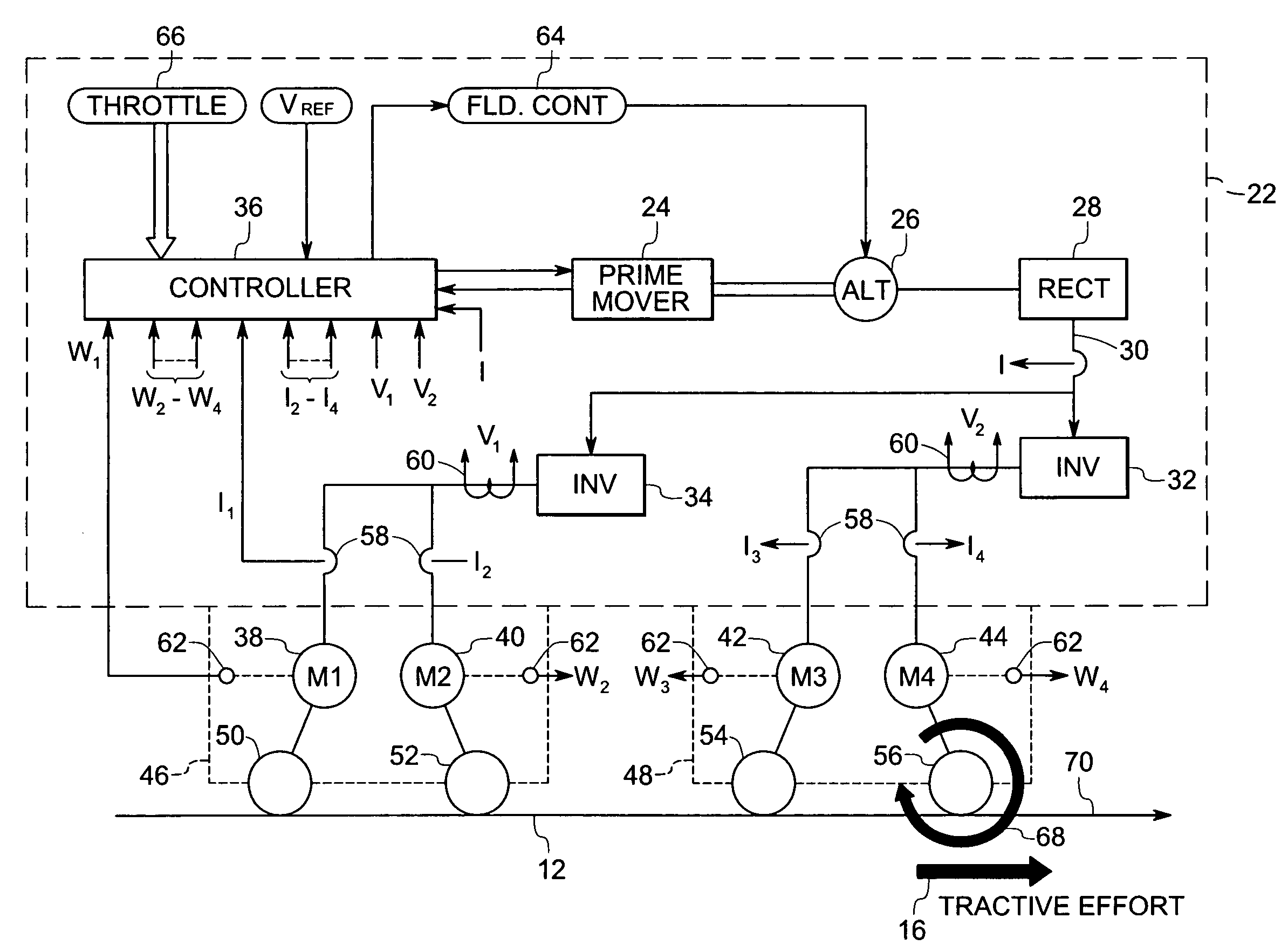
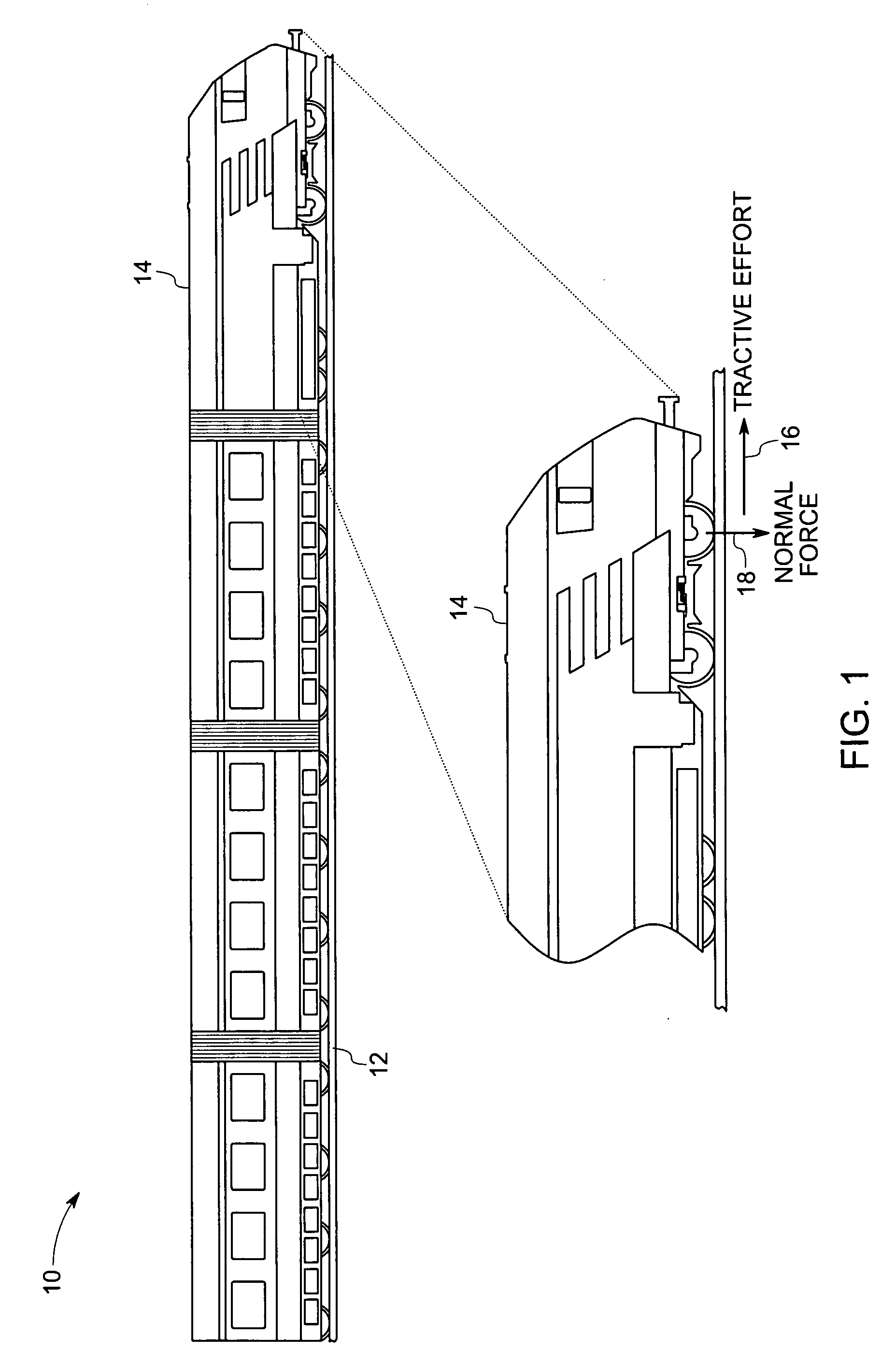
[0021]FIG. 1 is diagrammatical view of a train including a locomotive, and illustrating the tractive effort and adhesion of the locomotive controlled in accordance with an exemplary embodiment of this invention. The train 10 runs on rails 12. A locomotive 14 drives the train by means of electric traction motors at each axle-wheel set, as described in greater detail below. In the motoring mode of operation, these traction motors exert torque to the vehicle wheels, which exert tangential force or tractive effort on the surface such as the parallel steel rails of a railroad track on which the ve...
PUM
 Abstract
Description
Claims
Application Information