Stationary position detection circuit and motor drive circuit
a detection circuit and motor technology, applied in the direction of electronic commutators, process and machine control, instruments, etc., can solve the problems of large kickback voltage, increased cost and bulkiness, and inability to properly star
- Summary
- Abstract
- Description
- Claims
- Application Information
AI Technical Summary
Benefits of technology
Problems solved by technology
Method used
Image
Examples
first embodiment
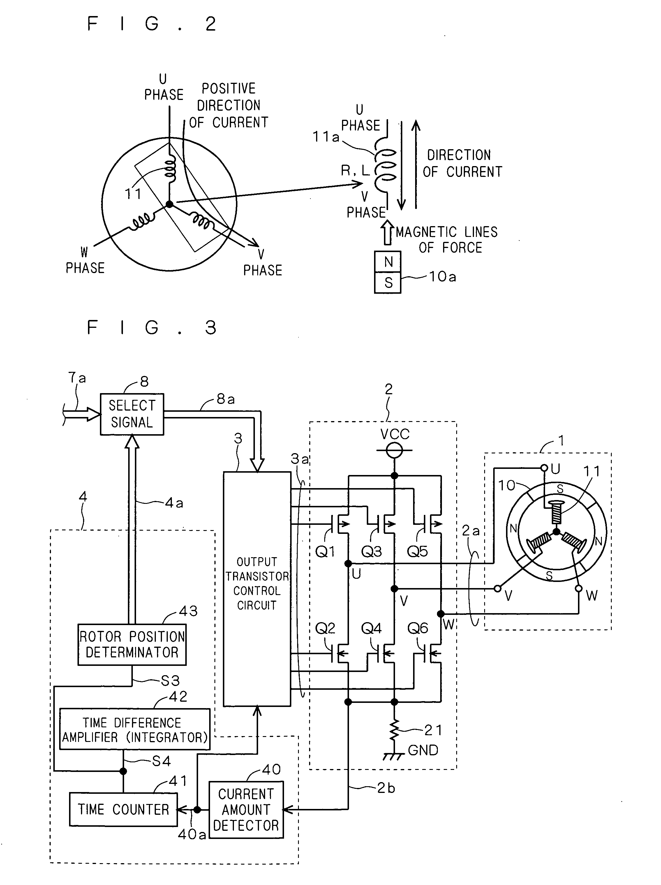
[0038] According to the first embodiment, there are provided a stationary position detection circuit and a motor drive circuit in which an alternating current is supplied to a motor load and the time during which the current flows in a first direction and the time during which the current flows in a second direction opposite to the first direction are converted into electrical signals, which are amplified to determine the position of the motor rotor in stationary mode according to the value of the electrical signals.
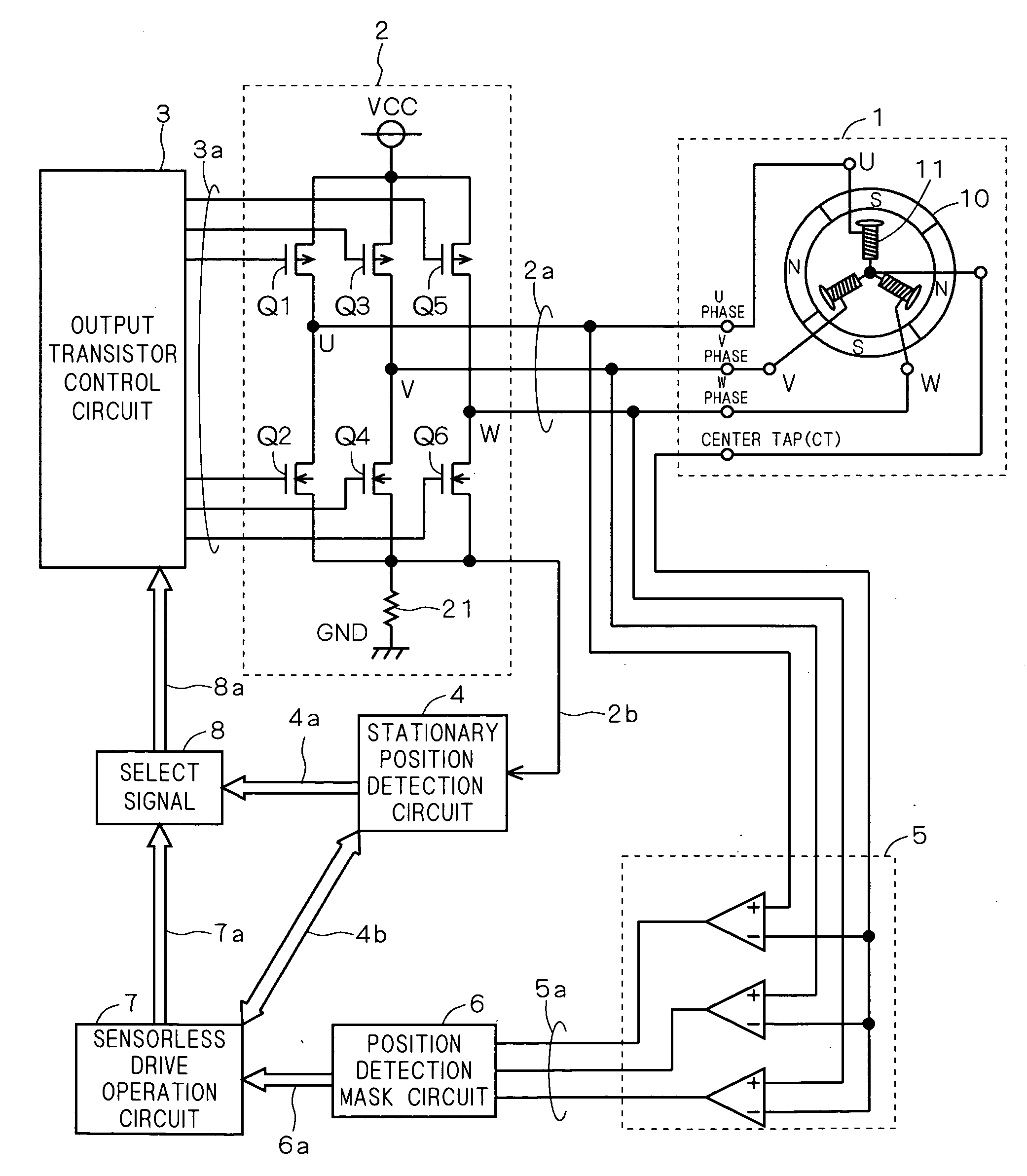
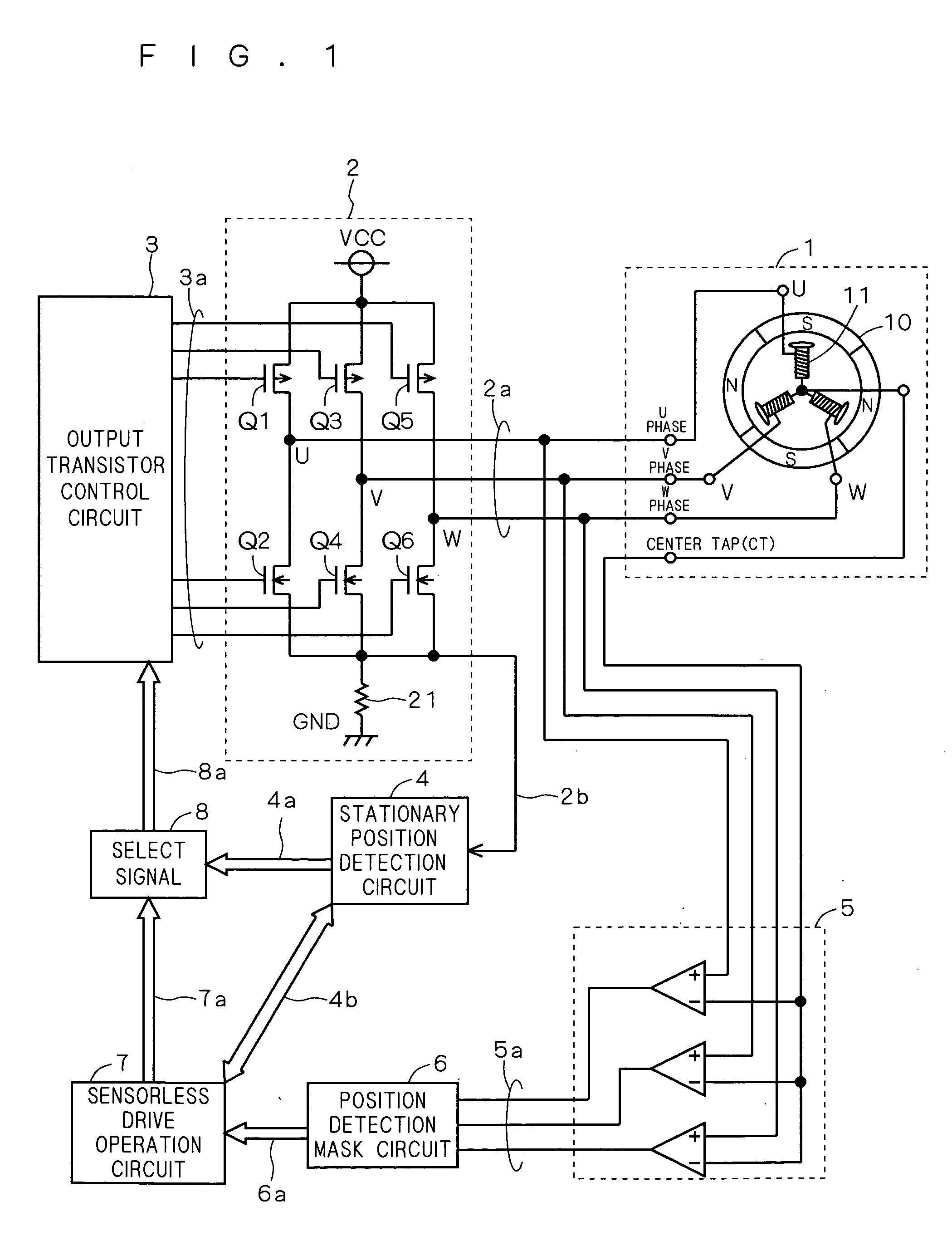
[0039]FIG. 1 is a diagram showing a motor drive circuit and a motor according to this embodiment. As shown in FIG. 1, the motor 1 is, for example, a three-phase DC brushless Hall sensorless motor including a rotor 10 of a permanent magnet and a stator 11 configured of a three-phase load with an armature coil wound on a field core. The load of the stator 11 exists for each of the phases U, V, W and coupled to each other at a center tap (CT).
[0040] The motor drive circui...
second embodiment
[0105] This embodiment is a modification of the stationary position detection circuit and the motor drive circuit according to the first embodiment, and represents another example of the configuration including the time counter 41 and the time difference amplifier 42 according to the first embodiment.
[0106]FIG. 16 is a diagram showing a detailed configuration of the time counter 41a and the time difference amplifier 42a in the stationary position detection circuit 4 according to this embodiment. The time counter 41a includes first and second current sources 410, 413, a first switch 411 for selectively outputting the current I1 from the first current source 410 when the logic value of the detection signal 40a is Low, and a second switch 412 for selectively drawing the current I1 to the second current source 413 when the logic value of the detection signal 40a is Hi. The current output from the first switch 411 and the current drawn by the second switch 412 constitute a current signa...
third embodiment
[0119] This embodiment is also a modification of the stationary position detection circuit and the motor drive circuit according to the first embodiment, and represents another example of the configuration of the time counter 41 and the time difference amplifier 42 according to the first embodiment.
[0120]FIG. 17 is a diagram showing a detailed configuration of a time counter 41b and a time difference amplifier 42b in the stationary position detection circuit 4 according to this embodiment. The time counter 41b includes a current source 410, a first switch 411 for selectively outputting the current I1 from the current source 410 when the logic value of the detection signal 40a is Low, a second switch 414 for applying a predetermined potential when the logic value of the detection signal 40a is Low, a third switch 415 for selectively outputting the current I1 from the current source 410 when the logic value of the detection signal 40a is Hi, a fourth switch 412 grounded when the logi...
PUM
 Abstract
Description
Claims
Application Information
 - R&D
- Intellectual Property
- Life Sciences
- Materials
- Tech Scout
- Unparalleled Data Quality
- Higher Quality Content
- 60% Fewer Hallucinations
Browse by: Latest US Patents, China's latest patents, Technical Efficacy Thesaurus, Application Domain, Technology Topic, Popular Technical Reports.
© 2025 PatSnap. All rights reserved.Legal|Privacy policy|Modern Slavery Act Transparency Statement|Sitemap|About US| Contact US: help@patsnap.com


