Fuel cell and separator for fuel cell

a fuel cell and separator technology, applied in the field of fuel cells, can solve the problems of reactant gas not flowing suitably, deformation of seal members into connection channels undetected, and inability to maintain desired sealing performance, etc., to achieve the effect of simple and compact structure and desired power generation performan

Inactive Publication Date: 2007-01-04
HONDA MOTOR CO LTD
View PDF6 Cites 14 Cited by
  • Summary
  • Abstract
  • Description
  • Claims
  • Application Information

AI Technical Summary

Benefits of technology

[0013] A main object of the present invention is to provide a fuel cell and a separator having simple and compact structure in which the water is discharged efficiently, and the desired power generation performance is achieved.
[0025] According to the present invention, the separator has the first and second openings. For example, the reactant gas flows from the reactant gas passage into the first opening, and then, the reactant gas is supplied from the second opening to the reactant gas flow field. In the structure, since the first and second openings are provided in the channel unit connecting the reactant gas passage and the reactant gas flow field, the flow field resistance (pressure loss) is increased effectively. Thus, the water is discharged from the channel unit efficiently.
[0026] Therefore, the reactant gas is supplied to the power generation area reliably, and the desired power generation performance is achieved. Further, the length of the channel unit is reduced, and the structure of the channel unit becomes simple and compact.
[0027] Further, in the present invention, the coolant flow field is provided for every two or more unit cells. Further, the common channel connected to the reactant gas passage is formed between the first and second separators. Therefore, the reactant gas flows separately from the common channel into the first opening of the first separator and the opening of the second separator. In the structure, the number of grooves in the flow field is reduced, and the flow field structure is simplified effectively.

Problems solved by technology

However, at the time of tightening the separators, the membrane electrode assemblies, and seal members between these components, the seal member may be deformed into the connection channel undesirably.
Therefore, the desired sealing performance may not be maintained.
Further, if the connection channel is closed, the reactant gas does not flow suitably.
Consequently, the fuel gas and the oxygen-containing gas are not supplied to the power generation area of the MEA 3, and the desired power generation cannot be performed suitably.

Method used


Image

  • Fuel cell and separator for fuel cell
  • Fuel cell and separator for fuel cell
  • Fuel cell and separator for fuel cell

Examples


first embodiment

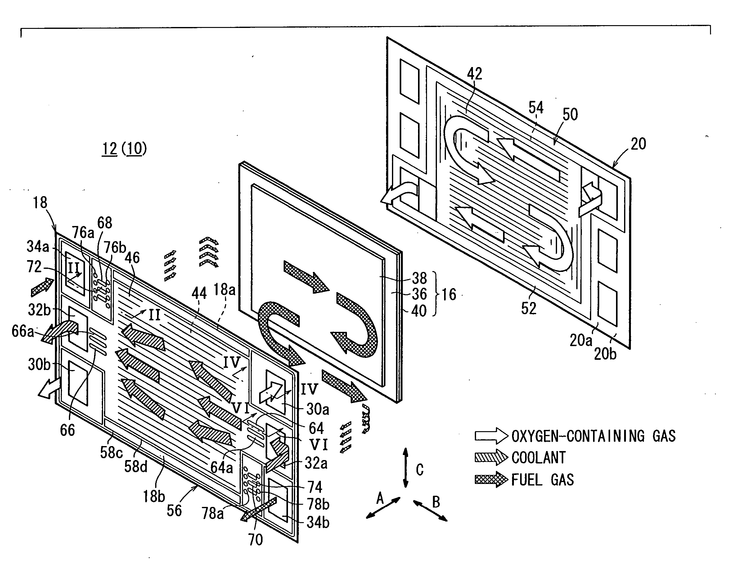
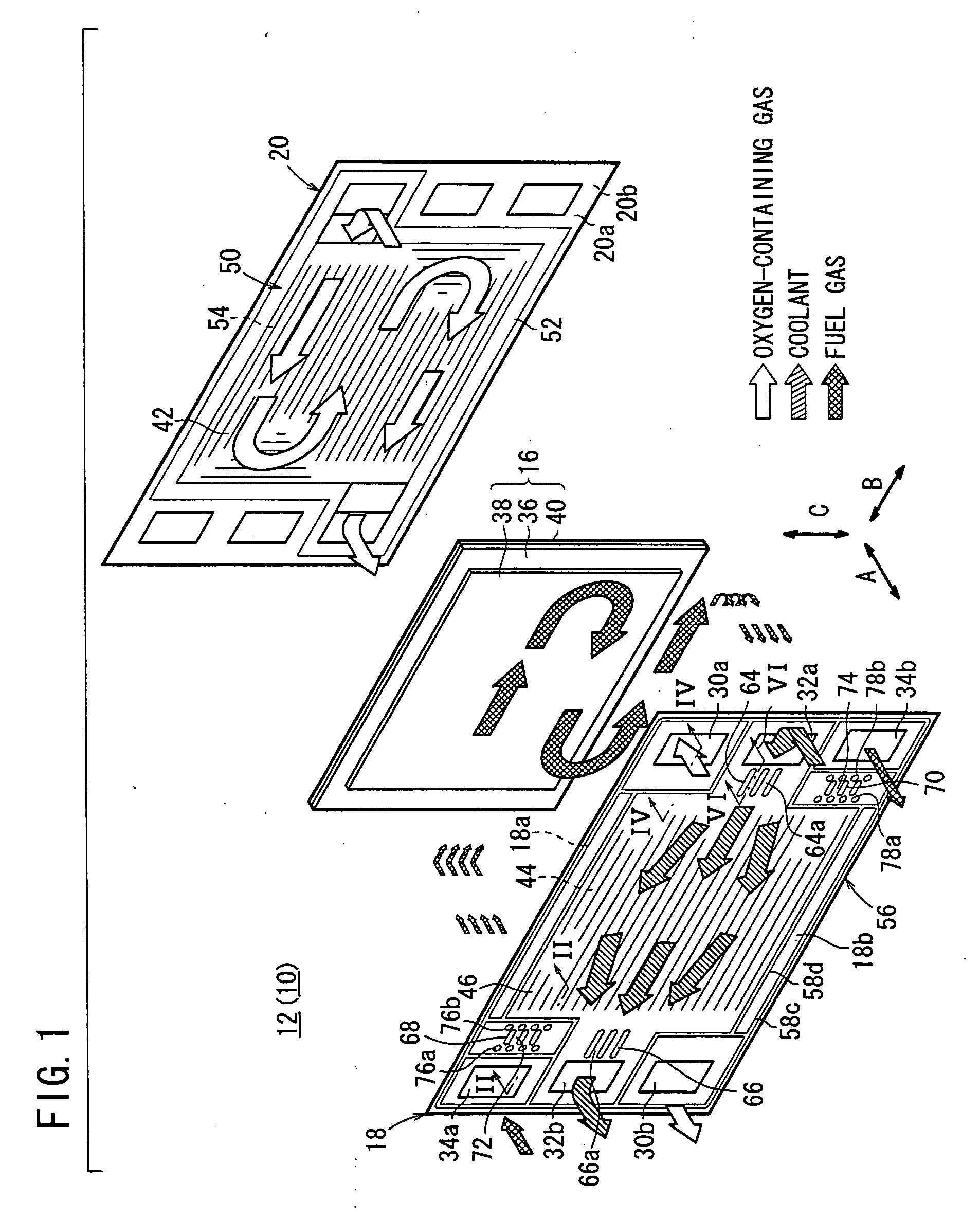
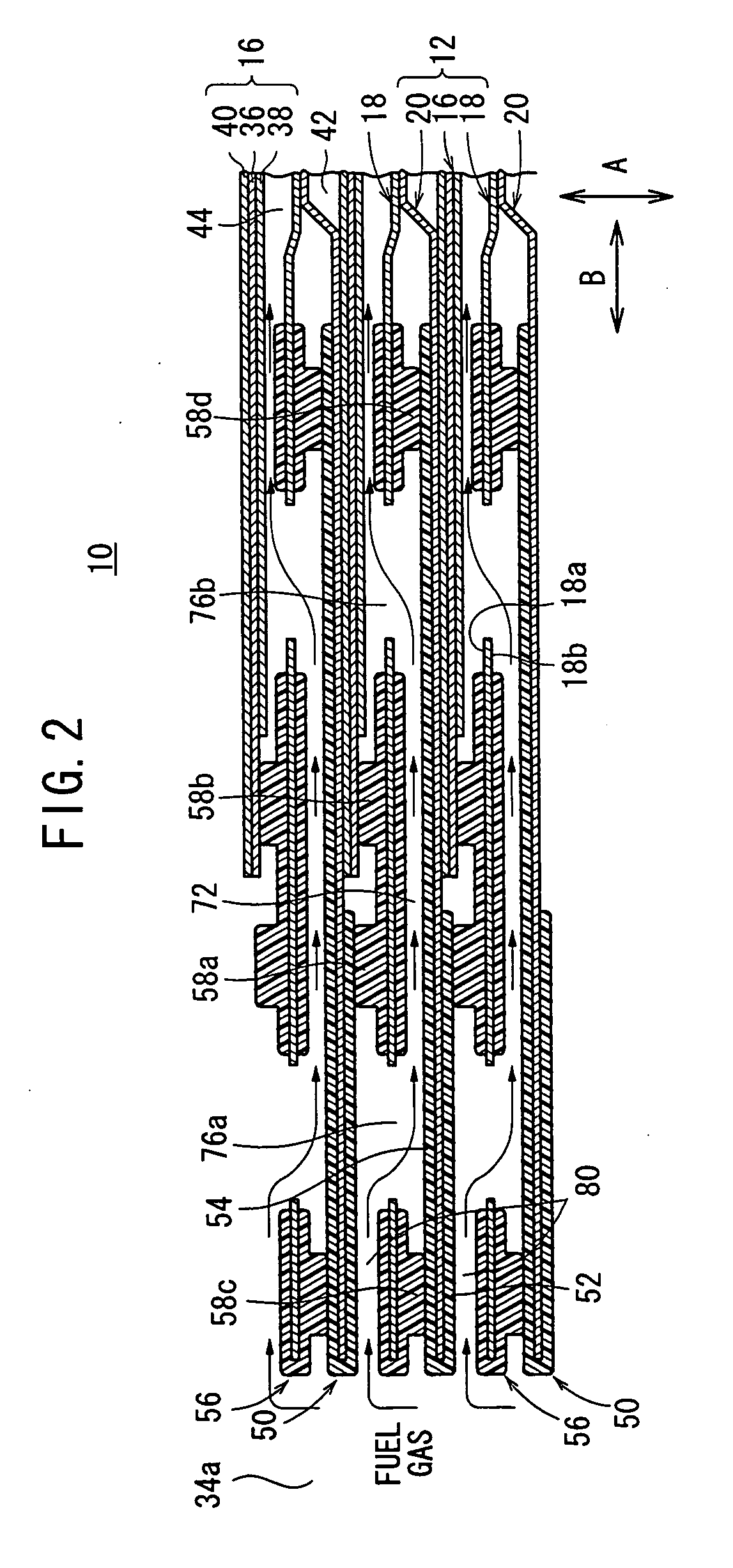
[0050]FIG. 1 is an exploded perspective view showing main components of a unit cell 12 of a fuel cell 10 according to the present invention. FIG. 2 is a cross sectional view showing the fuel cell 10 having stack structure formed by stacking a plurality of the unit cells 12 in a direction indicated by an arrow A, taken along a line II-II in FIG. 1.

[0051] As shown in FIG. 2, the fuel cell 10 has stack structure formed by stacking a plurality of the unit cells 12 in the direction indicated by the arrow A. The unit cell 12 includes a membrane electrode assembly (electrolyte electrode assembly) 16, and an anode side metal separator (one separator) 18 and a cathode side metal separator (the other separator) 20 sandwiching the membrane electrode assembly 16. For example, the anode side metal separator 18 and the cathode side metal separator 20 are steel plates, stainless steel plates, aluminum plates, plated steel sheets, or metal plates having surfaces subjected to anti-corrosive surface ...

third embodiment

[0086]FIG. 9 is an exploded view showing main components of a unit cell 102 of a fuel cell 100 according to the present invention. FIG. 10 is a cross sectional view showing the fuel cell 100.

[0087] The unit cell 102 includes a membrane electrode assembly 104 and an anode side metal separator 106 and a cathode side metal separator 108 sandwiching the membrane electrode assembly 104. The membrane electrode assembly 104 includes an anode 38, a cathode 40a, and a solid polymer electrolyte membrane 36a interposed between the anode 38 and the cathode 40a. The surface area of the solid polymer electrolyte membrane 36a is larger than the surface area of the anode 38 and the surface area of the cathode 40a.

[0088] As shown in FIGS. 10 and 11, the anode side metal separator 106 has a seal 110 as part of the second seal member 56 on its surface 18a facing the anode 38. The seal 110 is provided in the area corresponding to the outer end of the solid polymer electrolyte membrane 36a of the membr...

fourth embodiment

[0091]FIG. 12 is an exploded perspective view showing a unit cell 122 of a fuel cell 120 according to the present invention. FIG. 13 is a cross sectional view showing the unit cell 122 at the oxygen-containing gas inlet.

[0092] The unit cell 122 includes a membrane electrode assembly 16 and an anode side metal separator 124 and a cathode side metal separator 126 sandwiching the membrane electrode assembly 16. The cathode side metal separator 126 has a plurality of first supply holes (first openings) 128a near the oxygen-containing gas supply passage 30a, and a plurality of second supply holes (second openings) 128b provided at positions spaced away from the first supply holes 128a toward the oxygen-containing gas flow field 42.

[0093] At the end of the oxygen-containing gas flow field 42, a plurality of first discharge holes (second openings) 130a are formed, and a plurality of second discharge holes (first openings) 130b are formed near the oxygen-containing gas discharge passage 30...


PUM

PropertyMeasurementUnit
areaaaaaaaaaaa
surface areaaaaaaaaaaa
unit cellsaaaaaaaaaa

Abstract

A unit cell of a fuel cell includes a membrane electrode assembly and an anode side metal separator and a cathode side metal separator sandwiching the membrane electrode assembly. A plurality of first supply holes and a plurality of second supply holes extend through a channel unit of the anode side metal separator, and the channel unit connects a fuel gas supply passage and a fuel gas flow field. A fuel gas from the fuel gas supply passage flows into the first supply holes, and flows through an inlet connection channel. The fuel gas flows into the second supply holes connected to an end of the inlet connection channel. The fuel gas flows toward the side of the membrane electrode assembly, and then, the fuel gas is supplied to an anode.

Description

BACKGROUND OF THE INVENTION [0001] 1. Field of the Invention [0002] The present invention relates to a fuel cell comprising unit cells. Each of the unit cells includes an electrolyte electrode assembly and separators sandwiching the electrolyte electrode assembly. The electrolyte electrode assembly includes a pair of electrodes, and an electrolyte interposed between the electrodes. A reactant gas passage extends through the separators for allowing at least one of a fuel gas and an oxygen-containing gas as a reactant gas to flow through the reactant gas passage. Further, the present invention relates to the separator for the fuel cell. [0003] 2. Description of the Related Art [0004] For example, a solid polymer electrolyte fuel cell employs a membrane electrode assembly (MEA) which includes an anode, a cathode, and an electrolyte membrane interposed between the anode and the cathode. The electrolyte membrane is a solid polymer ion exchange membrane. The membrane electrode assembly an...

Claims


Application Information

Patent Timeline
Patent Type & Authority Applications(United States)
IPC IPC(8): H01M8/02H01M2/08H01M8/04
CPCH01M8/0247H01M8/0258Y02E60/50H01M8/2405H01M2008/1095H01M8/0271H01M8/241H01M8/2483H01M8/0267H01M8/2457H01M8/0263
Inventor SUGITA, NARUTOSHIKOSAKA, TAKASHISATO, SHUJIMURO, TAKESHISAKANO, MASAAKI
Owner HONDA MOTOR CO LTD
Why Eureka
Try Eureka