Audio processor

Active Publication Date: 2007-01-04
PANASONIC SEMICON SOLUTIONS CO LTD
View PDF32 Cites 9 Cited by
  • Summary
  • Abstract
  • Description
  • Claims
  • Application Information

AI Technical Summary

Benefits of technology

[0027] With these configurations, it is possible to generate various audio clock si

Problems solved by technology

However, the determination of a frequency division ratio using such an equation tends to cause the problem of increase in circuit scale of an audio processor in a configuration in which a secti

Method used


Image

  • Audio processor
  • Audio processor
  • Audio processor

Examples


embodiment 1

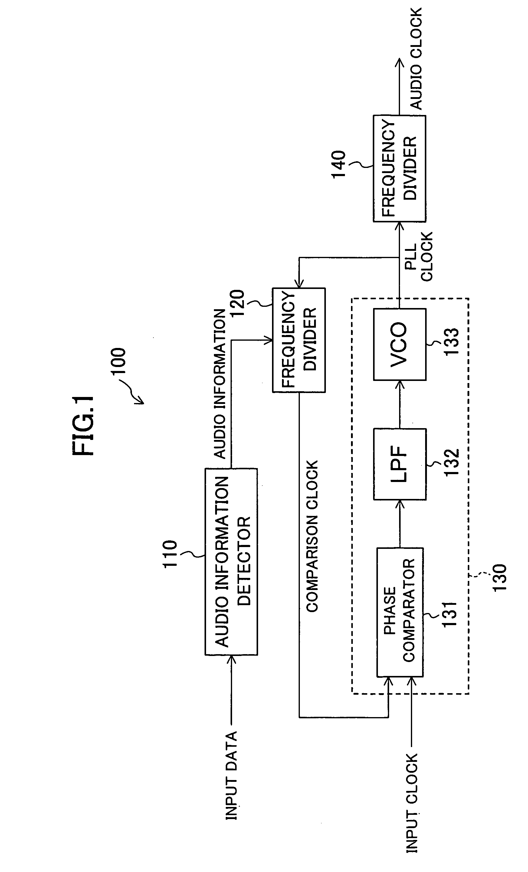
[0034]FIG. 1 is a block diagram illustrating a configuration of an audio processor 100 according to a first embodiment of the present invention. As illustrated in FIG. 1, the audio processor 100 includes: an audio information detector 110; a frequency divider 120; an analog PLL circuit 130; and a frequency divider 140.

[0035] The audio information detector 110 receives a packet (i.e., input data shown in FIG. 1) called an audio sample packet (ASP) in the HDMI standard. The ASP contains information called channel status bits (C bits). The C bits includes audio information such as sampling frequency information on audio data but is not conventionally used to obtain a frequency division ratio. The audio information detector 110 extracts frequency information on audio data from the C bits in the ASP and outputs the obtained information to the frequency divider 120 as audio information.

[0036] The frequency divider 120 determines a frequency division ratio based on the audio information ...

embodiment 2

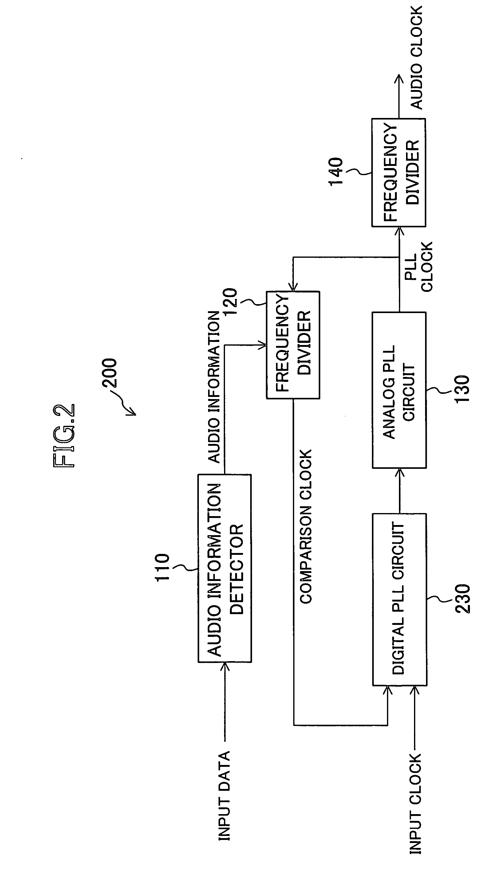
[0047]FIG. 2 is a block diagram illustrating a configuration of an audio processor 200 according to a second embodiment of the present invention. The audio processor 200 is different from the audio processor 100 of the first embodiment in that a digital PLL circuit 230 is additionally provided. In the following embodiments, each component with substantially the same function as in the first embodiment will be identified by the same reference numeral, and description thereof will be omitted.

[0048] The digital PLL circuit230 outputs, to an analog PLL circuit 130, a clock signal (i.e., a pre-PLL clock signal) whose phase has been changed such that an input clock signal and a comparison clock signal are synchronized with each other.

[0049] The foregoing configuration enables reduction of the lock time for the PLL circuit, as compared to such a case where only the analog PLL circuit 130 is provided as in the audio processor 100 of the first embodiment.

embodiment 3

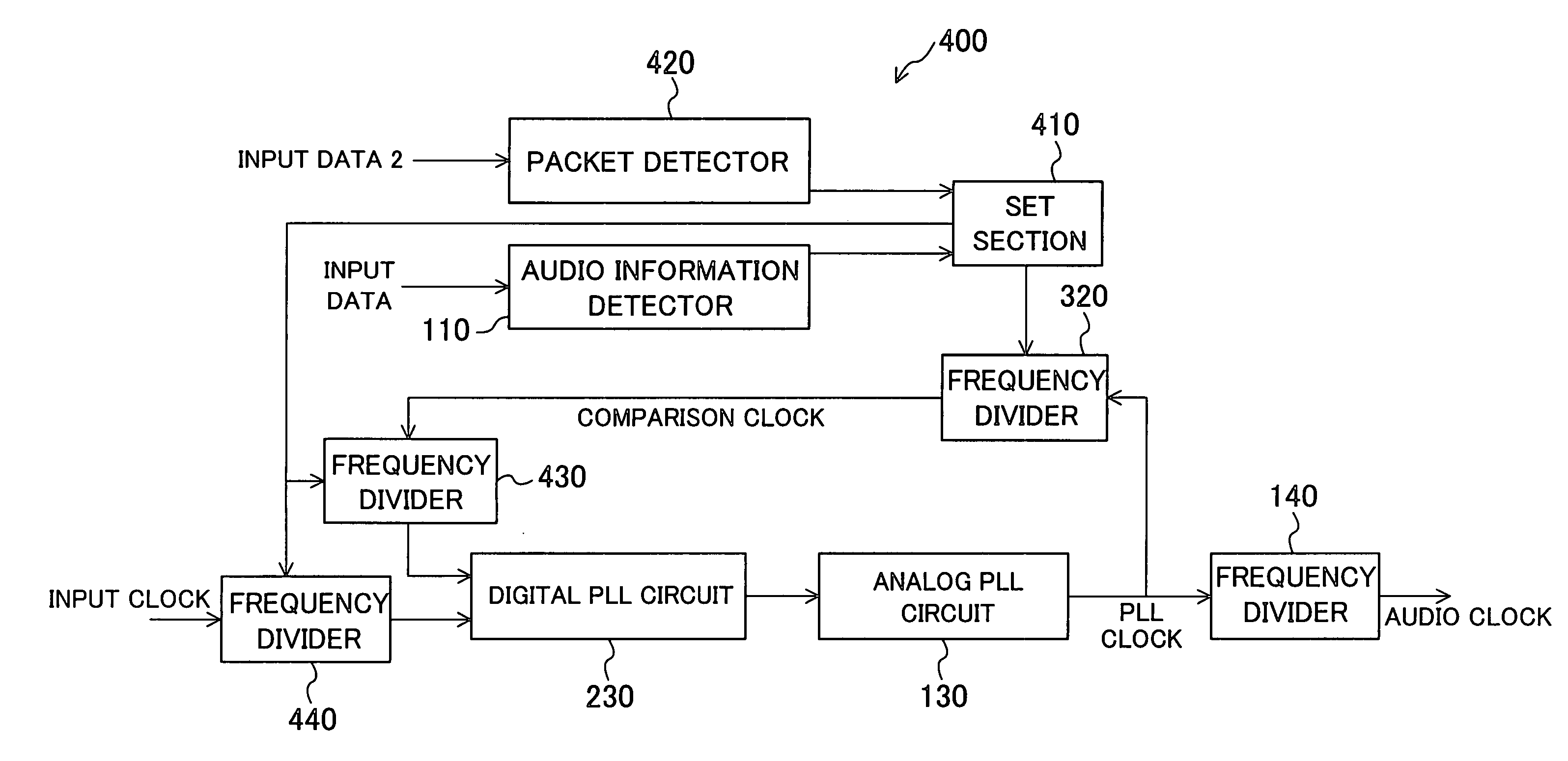
[0050]FIG. 3 is a block diagram illustrating a configuration of an audio processor 300 according to a third embodiment of the present invention. The audio processor 300 is different from the audio processor 200 in that a setting section 310 is additionally provided and the frequency divider 120 of the audio processor 200 is replaced by a frequency divider 320.

[0051] The setting section 310 determines a frequency division ratio based on audio information and sets the frequency division ratio in the frequency divider 320.

[0052] The frequency divider 320 performs frequency division on a PLL clock signal by the frequency division ratio set in the setting section 310 and outputs the determined frequency division ratio to a digital PLL circuit 230.

[0053] In this manner, the setting section 310 sets the frequency division ratio in the frequency divider 320, so that operation of, for example, the audio processor 300 is easily controlled using software.


PUM


Abstract

An audio information detector extracts frequency information on audio data from a packet called an ASP in the HDMI standard and outputs the extracted frequency information to a frequency divider as audio information. The frequency divider determines a frequency division ratio based on the audio information, divides the frequency of a PLL clock signal output from an analog PLL circuit by the frequency division ratio and outputs the resultant signal as a comparison clock signal. The analog PLL circuit performs feedback control such that the comparison clock signal and a reference clock signal are synchronized with each other, and generates an audio clock signal obtained by performing frequency multiplication or division on the reference clock signal.

Description

CROSS-REFERENCE TO RELATED APPLICATION [0001] The disclosure of Japanese Patent Application No. 2005-194984 filed on Jul. 4, 2005 including specification, drawings and claims is incorporated herein by reference in its entirety. BACKGROUND OF THE INVENTION [0002] 1. Field of the Invention [0003] The present invention relates to an audio processor for use in reproducing audio data transmitted through a digital interface such as an IEEE1394 interface or a high-definition multimedia interface (HDMI) for DVD players, digital television sets and AV amplifiers, for example. [0004] 2. Description of the Related Art [0005] With a digital interface such as an IEEE1394 interface or an HDMI, it is possible to select a rate (frequency) from a plurality of sampling rates to transmit audio data. [0006] In an audio processor for use in reproducing audio data transmitted through a digital interface as described above, to reproduce audio data, an audio clock signal having the same frequency as the sa...

Claims


Application Information

Patent Timeline
IPC IPC(8): G06F17/00
CPCH04S7/00
Inventor TAKAHASHI, SATOSHIKATO, SHUJI
Owner PANASONIC SEMICON SOLUTIONS CO LTD
Why Eureka
Try Eureka