Serving end use customers with onsite compressed air energy storage systems

a technology for onsite compressed air and end use customers, applied in combined combustion mitigation, machines/engines, gas turbine plants, etc., can solve the problem of not reducing the peak transmission and distribution capital requirements,

Inactive Publication Date: 2007-01-11
MECHANOLOGY INC
View PDF19 Cites 110 Cited by
  • Summary
  • Abstract
  • Description
  • Claims
  • Application Information

AI Technical Summary

Benefits of technology

[0011] This invention relates to development of an Energy Management Program (EMP) for end users to relieve them of high charges for energy and power demand from load serving entities (LSE) with use of compressed air energy storage (CAES) systems that do not need combustion to provide power for peak use on the customer side of the meter, creating a new method of doing business that makes development of CAES systems that are integrated into end user energy management programs (EMP) viable.

Problems solved by technology

CAES systems and technology placed on the generation side of the meter, usually close to the power plant, contribute nothing to reducing peak transmission and distribution capital requirements.

Method used


Image

  • Serving end use customers with onsite compressed air energy storage systems
  • Serving end use customers with onsite compressed air energy storage systems

Examples


Embodiment Construction

[0031] A description of preferred embodiments of the invention follows.

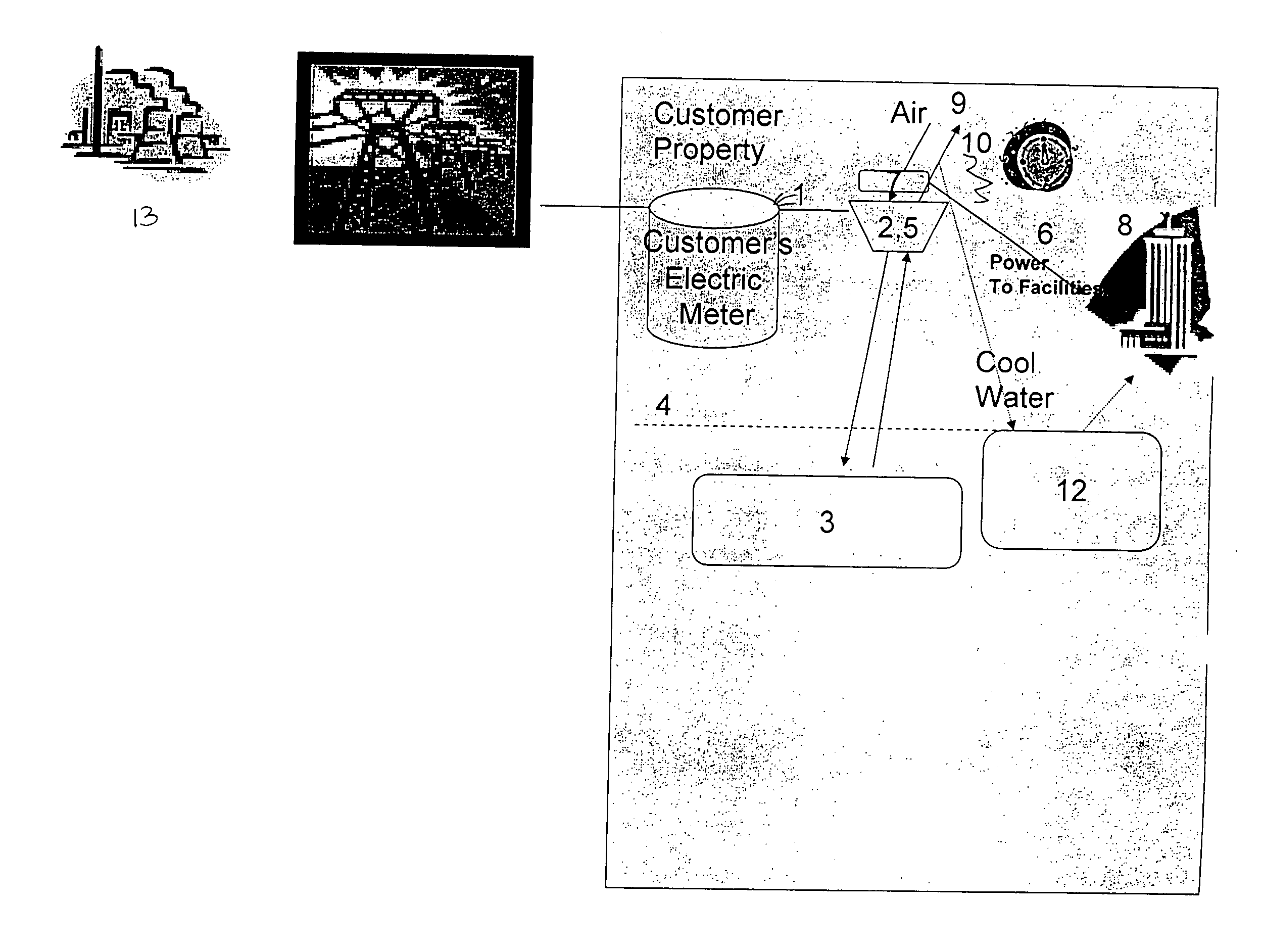
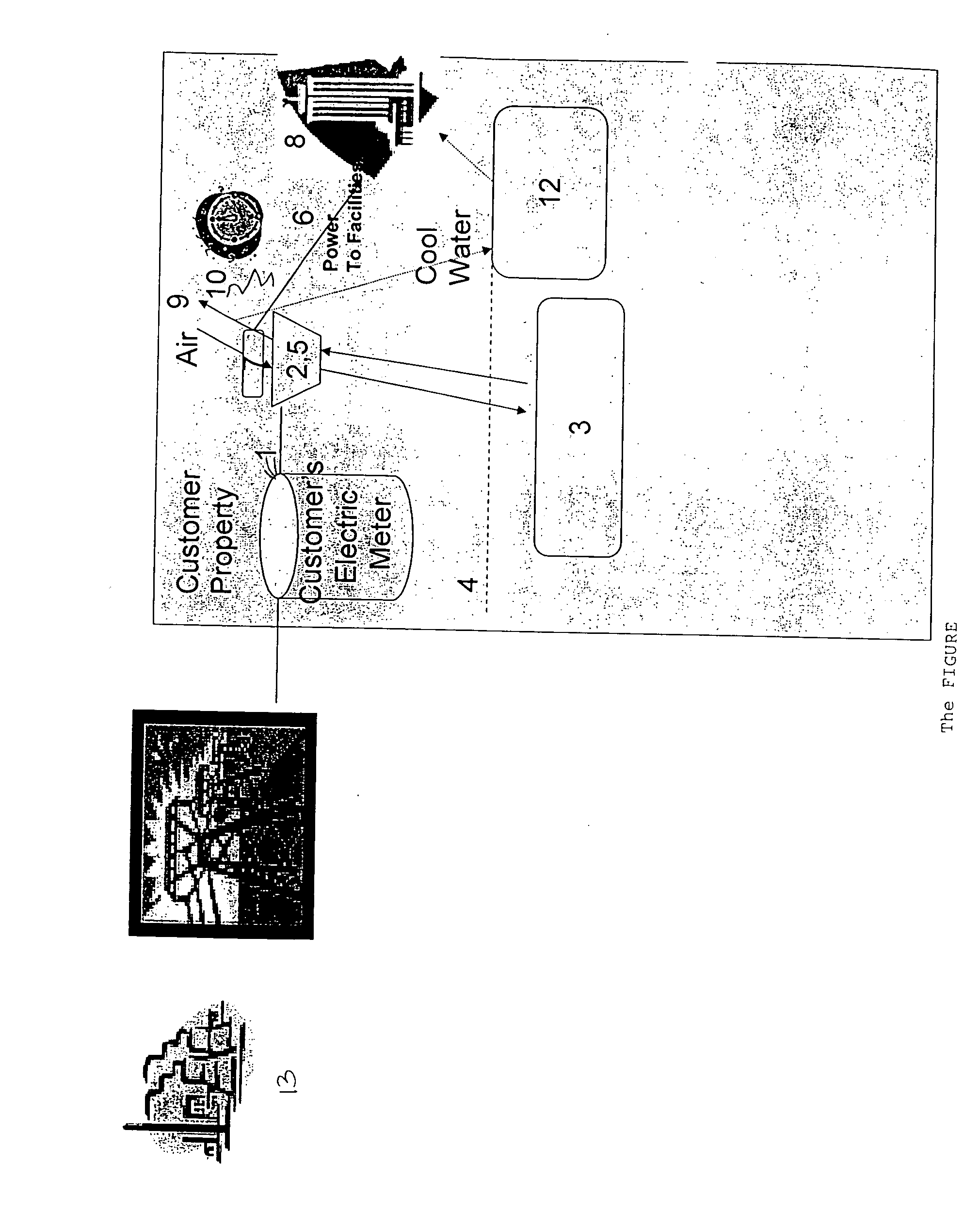
[0032] Referring to the FIGURE, the CAES system is built on the customer side of the meter 1 (i.e., “on-site”). This system consists of a compressor 2 that compresses a fluid, such as air, into storage container 3 that is, optionally, buried in the ground 4. The container is capable of withstanding high pressures. An expander 5 expands the compressed air when power is needed, usually during the period of peak power demand as indicated on the clock 6. The compressor 2 and expander 5 could be the same device or separate devices. The expander is operably connected to a generator 7, which converts the energy stored as compressed air into electricity. Power is then provided to the customer's facilities, using a generator that is part of the designed system to do so, preferably using low voltage suitable for the host facility 8. Cooling can also be extracted from the expanding air stream 9 and cools water in the water...


PUM


Abstract

The invention relates to systems for stored compressed air without use of combustion. The systems can be installed on the customer side of the meter and creates electricity during peak hours after it has been stored in off peak hours. The invention creates a financial incentive for conserving energy costs by building compressed air storage systems which heretofore have seen little application.

Description

RELATED APPLICATION SECTION [0001] This application claims benefit of priority to U.S. application No. 60 / 692,510 filed on Jun. 21, 2005, the teachings of which are incorporated herein by reference.BACKGROUND OF THE INVENTION [0002] End users of electricity, also called industrial, commercial and retail ratepayers by load serving entities (utilities that deliver power to the customers' meter), face unfortunate rate structures. During certain hours, usually the day and especially in the summer, load serving entities charge more per kilowatt hour (kWh) for electricity than at night. Additionally, many have a demand charge that is related to the highest power use during the day in a given month of season (a charge per kW of power where the charge might be $16 per kW even though that amount of power was only used for 15 minutes in a month). Since end users generally use more power and electricity during the day than at night, when rates are lowest, their costs for electricity and power ...

Claims


Application Information

Patent Timeline
Patent Type & Authority Applications(United States)
IPC IPC(8): F03G7/00
CPCF02C1/02Y02E60/15Y02E20/14F02C6/16Y02E60/16
Inventor HOFFMAN, JOHN S.INGERSOLL, ERICCHOMYSZAK, STEPHEN
Owner MECHANOLOGY INC
Why Eureka
Try Eureka