Methods and apparatus for reducing a sampling rate during a sampling phase determination process

a sampling rate and sampling phase technology, applied in the field of digital communication, can solve the problems of high sampling rate, higher power consumption, and more expensive hardware (e.g., units and/or buffer memory)

Active Publication Date: 2007-01-11
MALIKIE INNOVATIONS LTD
View PDF13 Cites 17 Cited by
  • Summary
  • Abstract
  • Description
  • Claims
  • Application Information

AI Technical Summary

Problems solved by technology

In high bandwidth communication systems (e.g. wireless local area network (WLAN) such as 802.11b), high sampling rates require more expensive hardware (e.g. analog-to-digital converter, digita

Method used


Image

  • Methods and apparatus for reducing a sampling rate during a sampling phase determination process
  • Methods and apparatus for reducing a sampling rate during a sampling phase determination process
  • Methods and apparatus for reducing a sampling rate during a sampling phase determination process

Examples


first embodiment

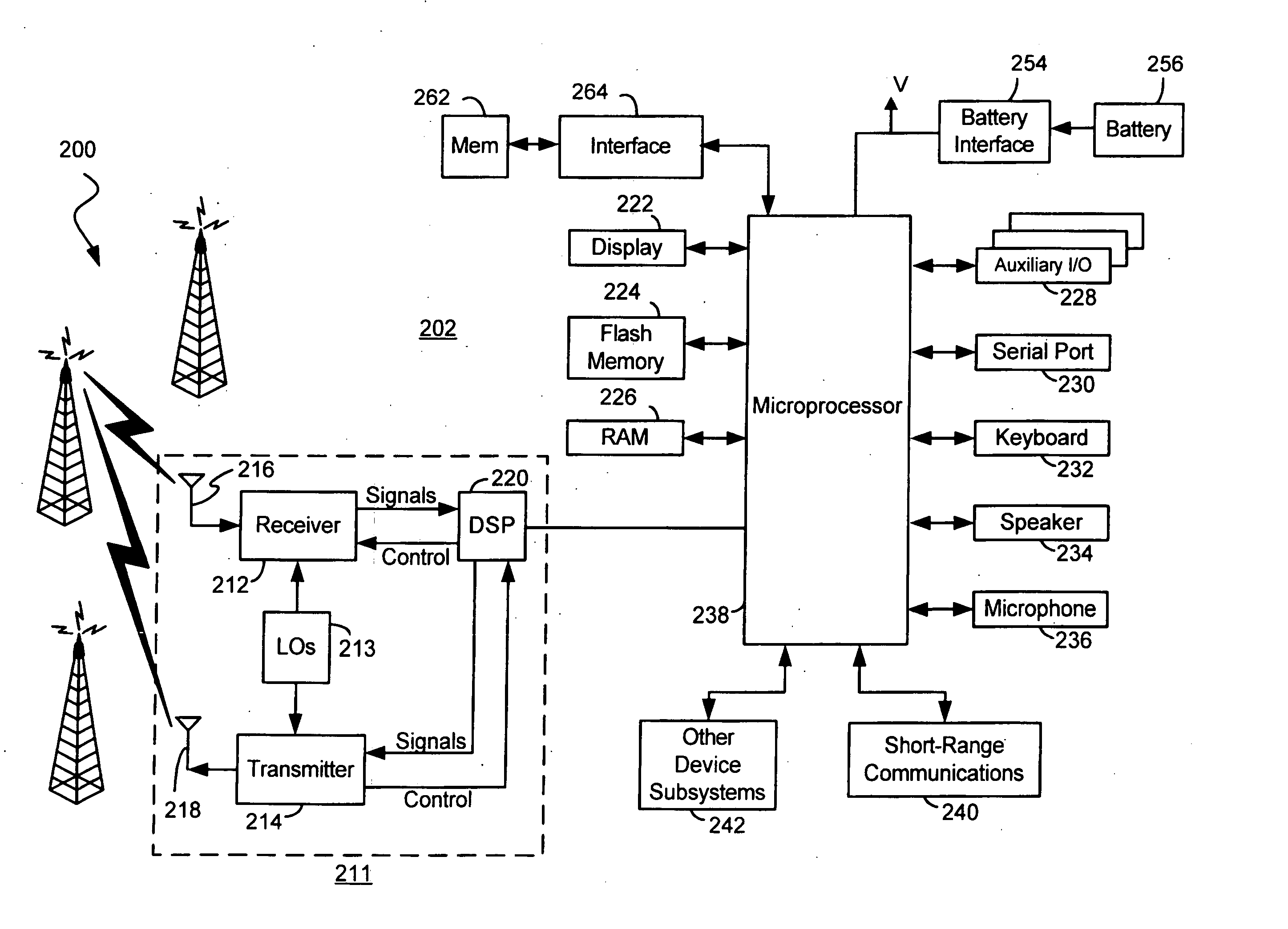
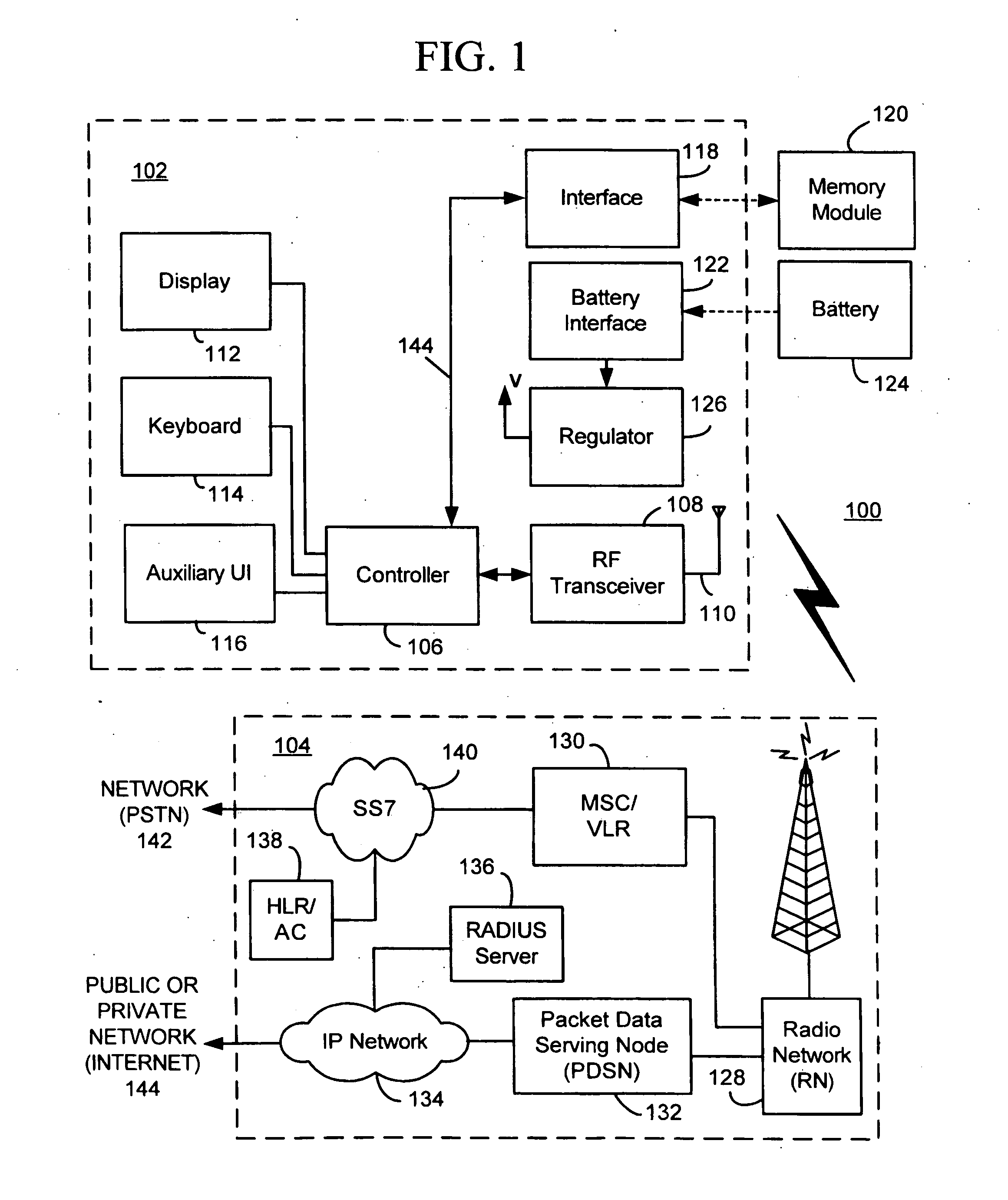
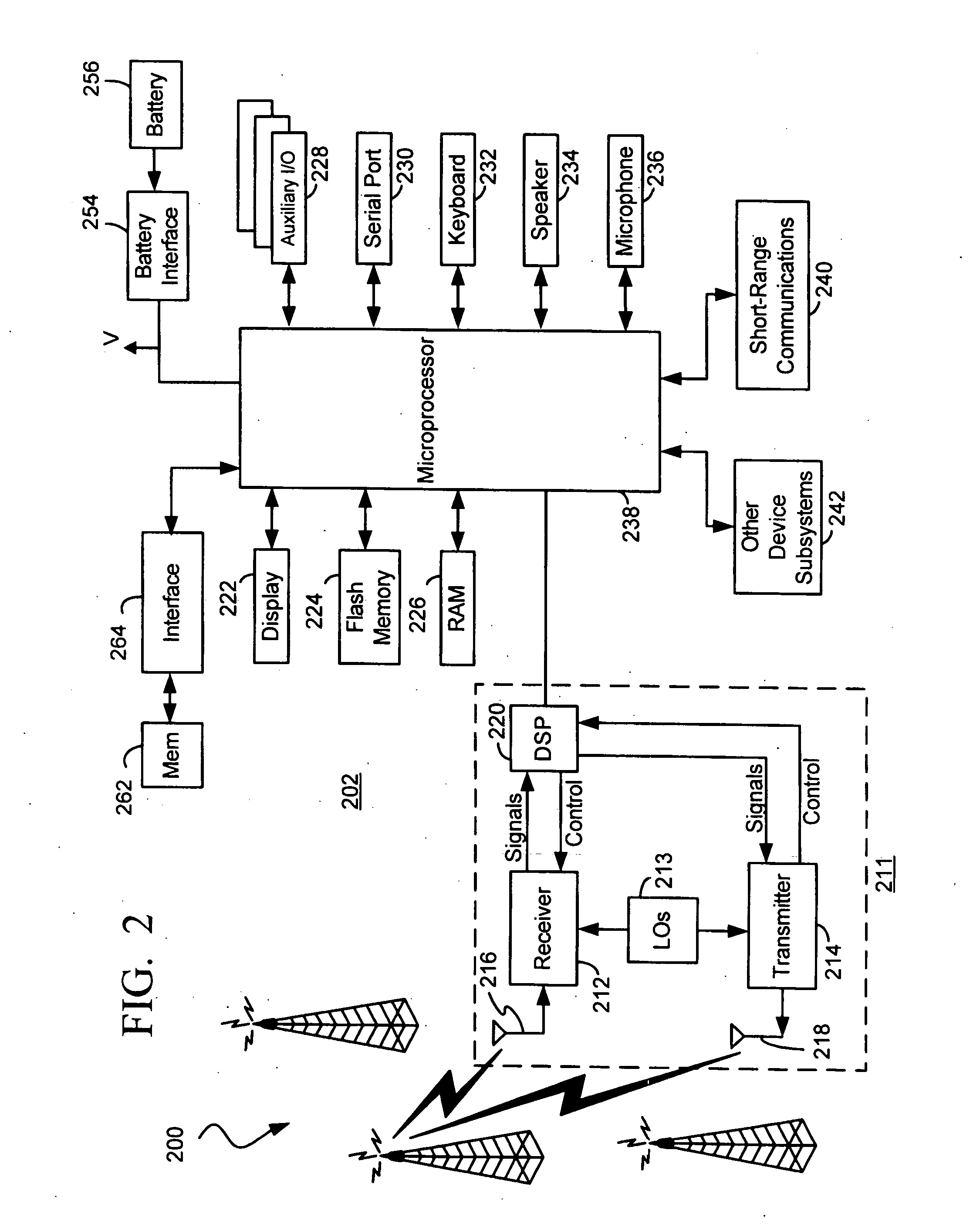
[0053]FIG. 8 shows circuitry which may be utilized to implement the techniques of the present application, as described in relation to FIGS. 5-7 above. The circuitry of FIG. 8 includes control circuitry or controller 810 (e.g. controller 106 of FIG. 1 or microprocessor 238 of FIG. 2), a frequency synthesizer 812 with phase control, and an analog-to-digital converter 820. Analog-to-digital converter 820 includes a sampler 802 and a quantizer 804. I and Q analog baseband signals are received-at inputs to sampler 802, which samples the signals to produce sampled I and Q baseband signals at its outputs. The sampled I and Q baseband signals are fed into inputs to quantizer 804, which quantizes the signals to produce digital I′ and Q′ baseband signals at its outputs. Sampler 802 has a clock input which is coupled to a clock output from frequency synthesizer 812. Frequency synthesizer 812 is adapted to produce, at its clock output, a sampling clock signal having one of a plurality of diffe...

second embodiment

[0056]FIG. 9 is circuitry which may be utilized to implement the techniques of the present application, as described in relation to FIGS. 5-8. The circuitry of FIG. 9 includes control circuitry or controller 810 (e.g. controller 106 of FIG. 1 or microprocessor 238 of FIG. 2), frequency synthesizer 812 having phase control, two analog-to-digital converters 820 and 920, an optimal phase determination block 908, and an information / signaling decoding block or decoder 910. Analog-to-digital converter 820 was described above in relation to FIG. 8 and operates in substantially the same way, except that it operates only on a received signal comprising the user or signaling information. I′ and Q′ outputs from quantizer 804 are coupled to information / signaling decoding block 910 to process information or signaling in a conventional fashion (e.g. despreading and decoding the information).

[0057] On the other hand, analog-to-digital converter 920 operates exclusively for the sampling phase deter...


PUM


Abstract

A received signal is sampled at a sampling period of T+m*(T/n) during a sampling phase determination process. T is a symbol or chip period of the received signal, n is a number of phases of the sampled signal, T/n is a phase resolution period, and m is a fixed non-zero integer value where −n<m<n (e.g. m=1 or −1). By sampling the received signal at the sampling period of T+m*(T/n), a sample set for each one of n phases of the sampled signal is produced. For each sample set, a correlation process is performed between the sample set and a predetermined correlation signal to produce a correlation result. Once an optimal correlation result is identified from the correlation process, the received signal is sampled at a sampling period of T at a phase associated with the optimal correlation result. Advantageously, oversampling at a sampling rate of n/T is not required during the sampling phase determination process, which reduces cost and power consumption.

Description

BACKGROUND [0001] 1. Field of the Technology [0002] The present invention relates generally to digital communications, and more particularly to methods and apparatus for reducing a sampling rate during a sampling phase determination process. [0003] 2. Description of the Related Art [0004] A wireless communication device, such as a mobile station operating in a wireless communication network, may provide for both voice telephony and packet data communications. The mobile station may, for example, be compatible with 3rd Generation (3G) communication standards (e.g. IS-2000) or utilize Global System for Mobile Communications (GSM), Time Division Multiple Access (TDMA), or Code Division Multiple Access (CDMA) wireless technologies. [0005] All such communications utilize radio frequency (RF) signal detection techniques in a wireless receiver. Here, RF signals are received through an antenna, amplified, and demodulated to recover a digital baseband signal having a symbol or chip period of...

Claims


Application Information

Patent Timeline
IPC IPC(8): H03M7/00
CPCH03M1/1255H04L7/042H04B1/709H04B1/7085
Inventor JIN, XIN
Owner MALIKIE INNOVATIONS LTD
Why Eureka
Try Eureka