Multimode optical fibre communication system

Inactive Publication Date: 2007-01-11
BROADCOM INT PTE LTD
View PDF74 Cites 111 Cited by
  • Summary
  • Abstract
  • Description
  • Claims
  • Application Information

AI Technical Summary

Benefits of technology

[0033] Preferably, there is a user adjustable setting for varying the controllable delay and/or varying the controllable gain facto

Problems solved by technology

An optical signal may be subject to numerous sources of noise and distortion, both in the generation of the signal and its transmission through an optical communications channel.
Sources of noise in an optical transmitter or receiver include thermal noise and shot noise.
A receiver section of the receiver may also use an avalanche photodiode for high sensitivity, but this will introduce avalanche photodiode noise.
The generation of an optical signal will in general be subject to other sources of noise or drift.
System distortion may be due to non-linear variations owing to the use of new or existing multimode optical fibre in an optical communications link.
In a multimode optical fibre, different modes have different propagation velocities, which te

Method used


Image

  • Multimode optical fibre communication system
  • Multimode optical fibre communication system
  • Multimode optical fibre communication system

Examples


Embodiment Construction

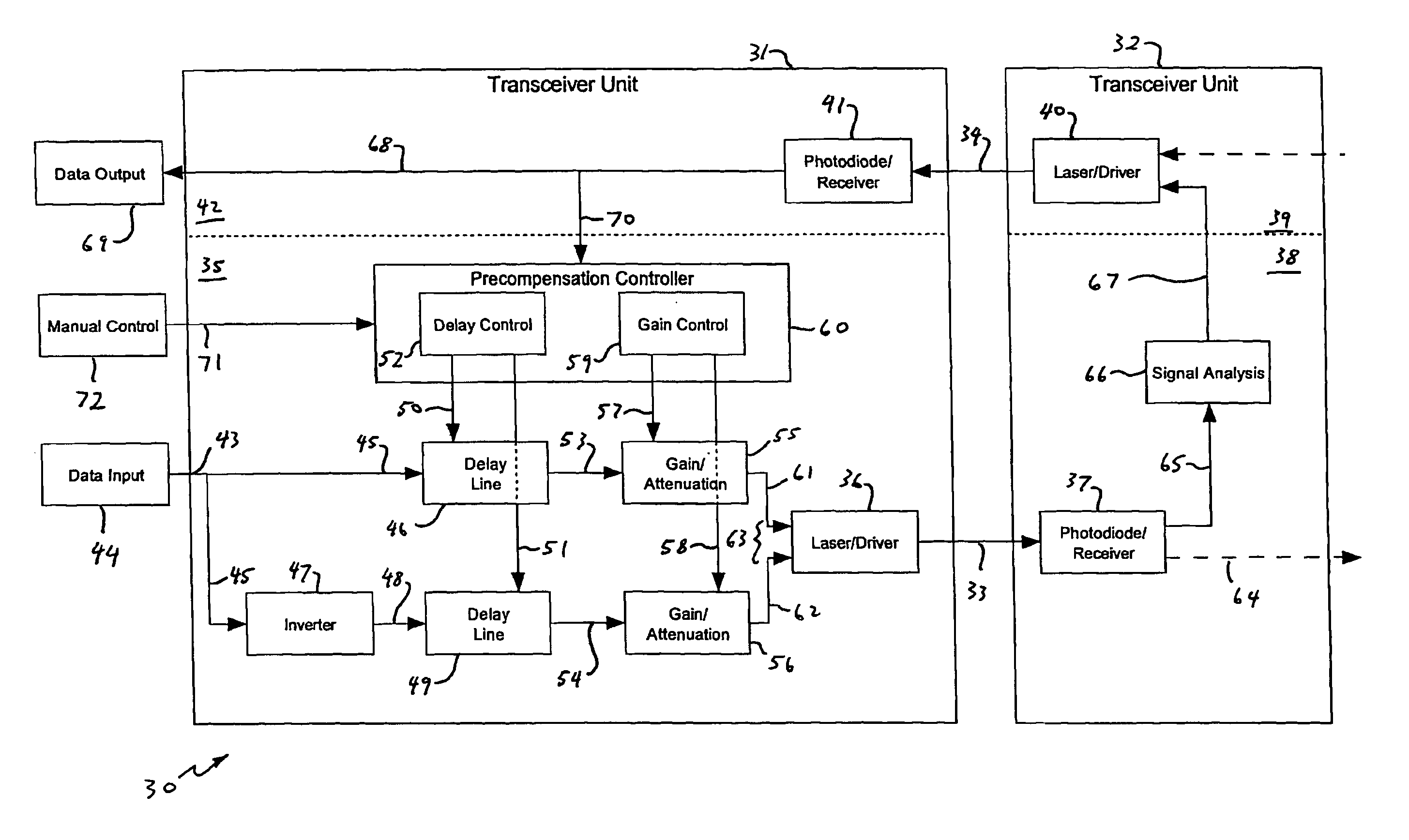
[0039]FIG. 1 illustrates one example of how an optical pulse 1 can become degraded during a transmission through a multimode optical fibre. The horizontal axis represents either time or distance along the length of the fibre and the vertical axis is the intensity of the transmitted optical radiation. There will, however, be considerable variability in the particular form of pulse distortion in a multimode optical fibre link, depending on a number of factors such as the type and length of the optical fibre.

[0040] Initially, the pulse 1 is narrow having a sharp rising edge 2 and a similarly sharp falling edge 3. As the pulse is transmitted along the length of the fibre, different modes travel at different speeds. The result is that the received pulse will be spread out, mainly along a trailing edge 4. The intensity of the received pulse will also drop somewhat, although in FIG. 1 the peak transmitted and received intensities are shown as being the same so that the change in shape of ...


PUM


Abstract

A multimode optical fibre communications system, and in particular to a system in which non-linearities in the propagation of the signal through a multimode optical communications channel degrade the signal presented to the receiver. The system includes an optical transmitter unit for connection to a multimode optical fibre transmission link. The transmitter unit has a data input for receiving an input data signal, a data signal processing circuit and a source of optical radiation. The data signal processing circuit is arranged to receive the input data signal from the data input and to provide a processed data signal to the source of optical radiation and the source of optical radiation is arranged to generate from this an optical signal for transmission by a multimode optical fibre. The data processing circuit is arranged to provide from the input data signal a non-inverted data signal and an inverted data signal, receive a control signal for controlling the generation of the processed data signal, apply a controllable delay in accordance with the control signal to at least one of the non-inverted and inverted data signals, and combine the non-inverted and inverted signals after the application of the controllable delay(s) and gain factor(s) to generate the processed data signal.

Description

BACKGROUND [0001] a. Field of the Invention [0002] The present invention relates to a multimode optical fibre communications system, and in particular to an optical fibre communications system in which non-linearities in the propagation of the signal through a multimode optical communications channel degrade the signal presented to the receiver. [0003] b. Related Art [0004] An optical signal may be subject to numerous sources of noise and distortion, both in the generation of the signal and its transmission through an optical communications channel. Sources of noise in an optical transmitter or receiver include thermal noise and shot noise. A receiver section of the receiver may also use an avalanche photodiode for high sensitivity, but this will introduce avalanche photodiode noise. The generation of an optical signal will in general be subject to other sources of noise or drift. For example, the output power of a laser diode will be subject to slow drift as it heats up in use or f...

Claims


Application Information

Patent Timeline
IPC IPC(8): H04B10/00H04B10/2581H04B10/40H04B10/50H04B10/58
CPCH04B10/2581H04B10/40H04B10/58H04B10/504
Inventor BOTHWELL, ANDREWMEADOWCROFT, SIMON
Owner BROADCOM INT PTE LTD
Why Eureka
Try Eureka