Optical recording medium and two layered optical recording medium, recording and reproducing method and recording and reproducing apparatus using media

Inactive Publication Date: 2007-01-11
RICOH KK
View PDF6 Cites 6 Cited by
  • Summary
  • Abstract
  • Description
  • Claims
  • Application Information

AI Technical Summary

Benefits of technology

[0017] In this situation, the present inventors have made extensive and intensive studies with respect to not only the barrier layer preventing the corrosion of the reflective layer comprising Ag or an Ag alloy, but also the barrier layer having advantageous light transmission properties for producing a recording layer composition comprising two recording layers.
[0018] Accordingly, it is an object of the present invention to provide an optical recording medium in which the corrosion of the reflective la

Problems solved by technology

The mechanism of corrosion of Ag or an Ag alloy used for producing the reflective layer of the optical information recording medium is not completely yet clarified; however it is generally thought that when the reflective layer is produced using Ag or an Ag alloy, Ag or an Ag alloy is sulfurated by sulfur-impurities in a dielectric layer comprising a mixture of ZnS and SiO2, so that the reflective layer is deteriorated.
However, the present inventors have measured the optical extinction coefficient k and the optical transmittance of a barrier layer (or an intermediate layer) which is disposed in an optical recording medium of multi-layer type and it was found as the result of the measurement that the barrier layer (or the intermediate layer) had a high optical extinction coefficient k and a low optical transm

Method used


Image

  • Optical recording medium and two layered optical recording medium, recording and reproducing method and recording and reproducing apparatus using media
  • Optical recording medium and two layered optical recording medium, recording and reproducing method and recording and reproducing apparatus using media
  • Optical recording medium and two layered optical recording medium, recording and reproducing method and recording and reproducing apparatus using media

Examples


Example

EXAMPLE 1

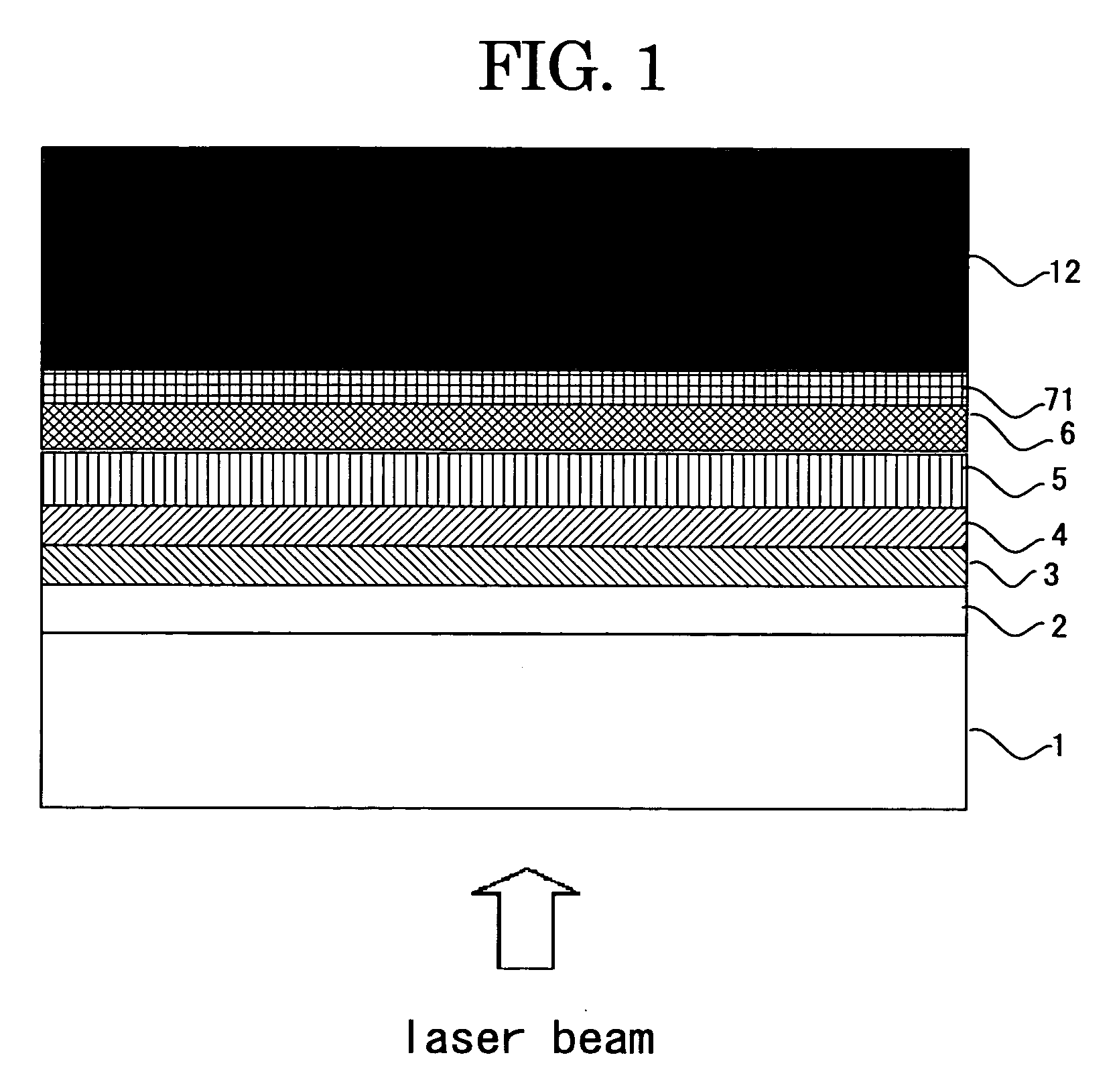
[0157] On the first substrate 1 made of a polycarbonate having a thickness of 0.6 mm which has a wobbling continuous groove (having the land and groove having a track pitch of 0.46 μm for the tracking guide) formed on the surface of the substrate, each layer of the optical recording medium was disposed using a magnetron sputtering apparatus.

[0158] The first dielectric layer 2 was produced using a mixture of ZnS and SiO2 (in molar ratio of 80:20) in such a manner that the layer has a thickness of 50 nm. The thermal conductivity of a mixture of ZnS and SiO2 was measured and found to be 0.66 W / m·K.

[0159] The first recording layer 3 was produced using Ge7Sb74.5Te18.5 (coefficients represent the atomic %) in which the recording and erasing can be performed with a linear velocity of 6 m / s in such a manner that the first recording layer 3 has a thickness of 6 nm.

[0160] The second dielectric layer 4 was produced using an oxide mixture dielectric comprising ZrO2 and Nb2O5 (in a ...

Example

EXAMPLES 2 AND 3

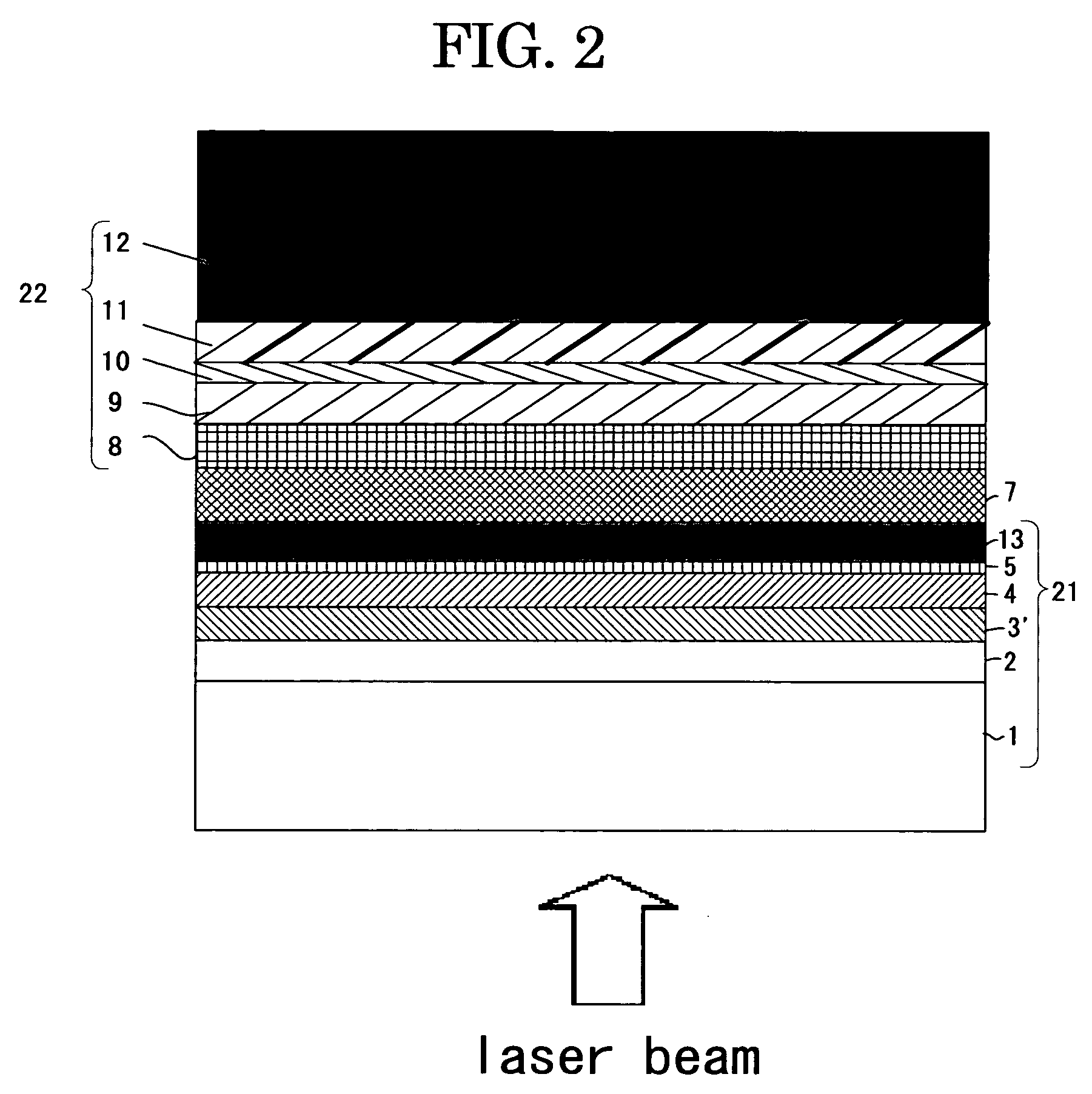
[0180] In Examples 2 and 3, the two-layered optical recording medium was produced in substantially the same manner as in Example 1, except that the material and the thickness of the second dielectric layer of Example 1 was changed to the material and the thickness (respectively in Examples 2 and 3) shown in Table 1 and the produced recording material was evaluated in the same manner as in Example 1. The mixing rate of materials shown in Table 1 is expressed in the molar ratio.

[0181] As the result of the evaluation shown in Table 1, the jitter of each of the produced recording media in Examples 1 to 3 after the 1,000 times repeating of the recording and erasing was so low as 9% or less and the change of the preservation properties thereof after the test for 300 hours was 1% or less. Moreover, the results of the reflectances thereof were 8% and 7.5%, respectively.

Example

EXAMPLES 4 AND 5

[0182] On the first substrate 1 made of a polycarbonate having a thickness of 0.6 mm which has a specified guide groove formed on the surface of the substrate, each layer of the optical recording medium was disposed using a magnetron sputtering apparatus.

[0183] The first dielectric layer 2 was produced using a mixture of ZnS and SiO2 (in molar ratio of 80:20) in such a manner that the layer has a thickness of 50 nm. The thermal conductivity of a mixture of ZnS and SiO2 was measured and found to be 0.66 W / m·K.

[0184] The first recording layer 3 was produced using Ge3.5Sb72Te24.5 (coefficients represent the atomic %) in which the recording and erasing can be performed with a linear velocity of 6 m / s in such a manner that the first recording layer 3 has a thickness of 12 nm.
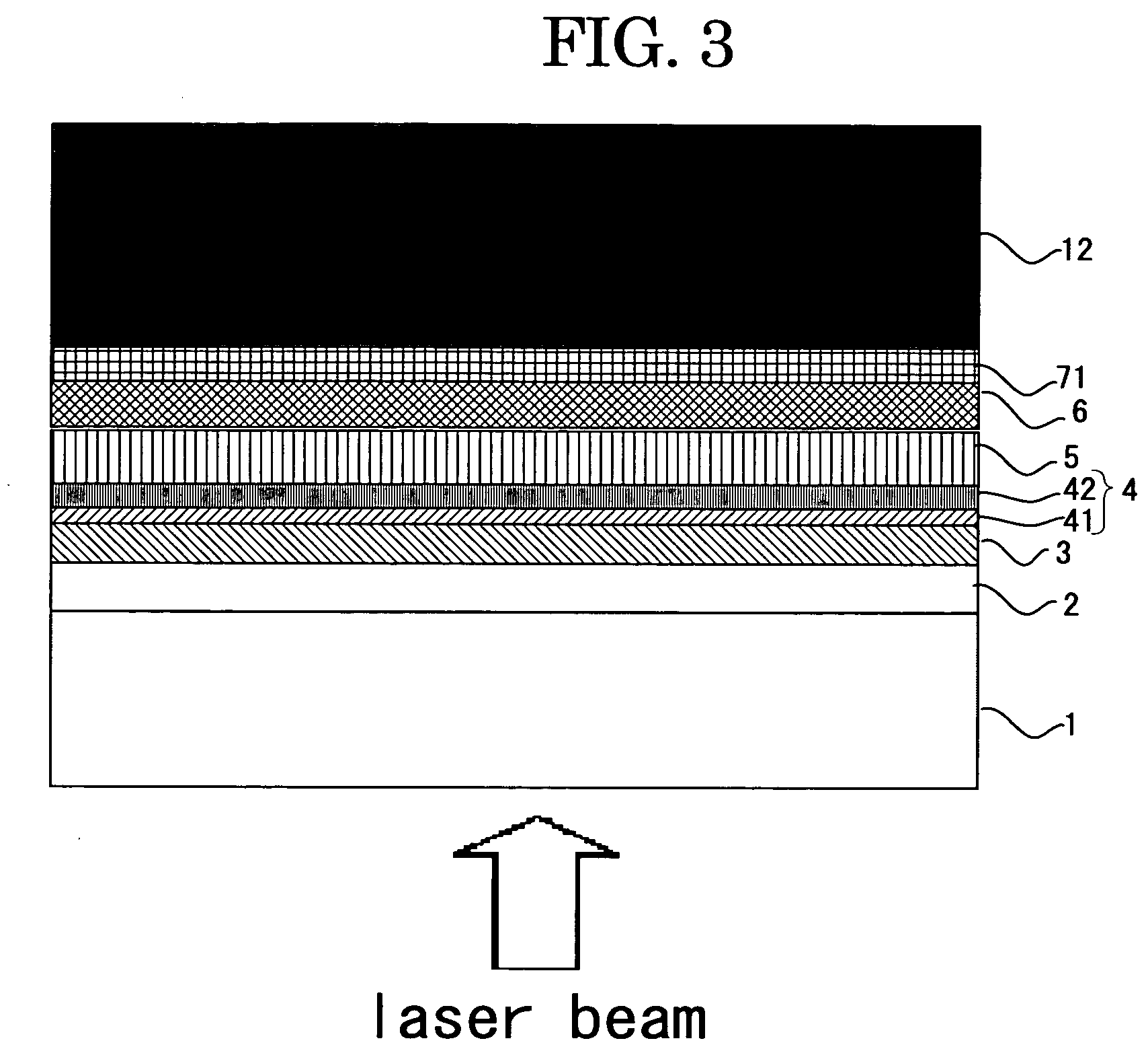

PUM


Abstract

The present invention provides an optical recording medium comprising a transparent first substrate and a first dielectric layer, a recording layer, a second dielectric layer and a reflective layer which are laminated on the first substrate in this order, wherein the recording layer comprises a thin layer comprising mainly an alloy represented by the composition formula: GexSbyTez (wherein x, y and z represent respectively an atomic %, and x, y and z satisfy respectively the following equations: 3.5≦x≦10, 70≦y≦80 and z=100−x−y) and the second dielectric layer comprises a thin film of a compound oxide comprising at least one of a mixture of Nb2O5 and ZrO2, a mixture of Nb2O5 and ZnO and a mixture of Nb2O5, ZrO2 and ZnO.

Description

CROSS-REFERENCE TO RELATED APPLICATIONS [0001] This is a continuation of Application No. PCT / JP2005 / 005459, filed on Mar. 17, 2005.BACKGROUND OF THE INVENTION [0002] 1. Field of the Invention [0003] The present invention relates to an optical recording medium (hereinafter, sometimes referred to as “optical information recording medium”, “phase-changing optical recording medium” or “phase-changing optical information recording medium”) and a two layered optical recording medium (hereinafter, sometimes referred to as “two layered optical information recording medium”, “two layers phase-changing optical recording medium” or “two layers phase-changing optical information recording medium”), which are excellent in environmental resistance, when they comprise in the reflective layer Ag or an Ag alloy as well as a recording and reproducing method and a recording and reproducing apparatus using the above-noted optical recording media. [0004] 2. Description of the Related Art [0005] Among th...

Claims


Application Information

Patent Timeline
IPC IPC(8): B32B3/02G11B7/00G11B7/24038G11B7/243G11B7/2433G11B7/257G11B7/2578G11B7/258G11B7/259
CPCG11B7/24038G11B7/2433G11B7/2578G11B7/259G11B2007/25715G11B2007/24314G11B2007/24316G11B2007/25706G11B2007/24312
Inventor SHINKAI, MASARUSHINOTSUKA, MICHIAKIIWASA, HIROYUKI
Owner RICOH KK
Why Eureka
Try Eureka