Bearing material coated slide member and method for manufacturing the same

a technology of bearing material and slide member, which is applied in the direction of connecting rod bearings, instruments, heat measurement, etc., can solve the problems of deterioration of anti-seizing properties, low productivity, and poor anti-seizing properties, so as to other properties, and improve the anti-seizing properties of the sliding surface.

Inactive Publication Date: 2007-01-11
TOYOTA JIDOSHA KK
View PDF14 Cites 10 Cited by
  • Summary
  • Abstract
  • Description
  • Claims
  • Application Information

AI Technical Summary

Benefits of technology

[0012] The present invention provides a method for manufacturing a bearing material coated slide member in which a bearing material is coated on a sliding surface of a slide member. The method for manufacturing a bearing material coated slide member comprises a bearing member coating step of forcing the bearing material to impact on the sliding surface in a state where the bearing material is in a solid phase to form a bearing material coated layer, and the bearing material comprises an Sn containing alloy powder. With this method, Sn can be dispersed in the bearing material coated layer, to thereby improve an anti-seizing property of the sliding surface.
[0013] In the method for manufacturing a bearing material coated slide member according to the present invention, the Sn containing alloy power may preferably be an Al alloy powder which contains 4 wt % to 16 wt % of Sn, or a Cu alloy powder which contains 2 wt % to 10 wt % of Sn. More preferably, the Sn containing alloy powder may be an Al alloy powder which contains from 8 wt % to 16 wt % of Sn, or a Cu alloy powder which contains from 5 wt % to 10 wt % of Sn. Use of the Al alloy powder or the Cu alloy powder containing Sn which is of a composition as described above can yield further improvement in anti-seizing property of the sliding surface.
[0015] In the bearing material coated slide member according to the present invention manufactured by coating a bearing material on a sliding surface of a slide member, the bearing material is caused, in a solid phase, to impact on the sliding surface to form a bearing material coated layer, and is prepared so as to include an alloy powder which contains Sn. Because Sn can be dispersed in the bearing material coated layer, the anti-seizing property and other properties can be improved.
[0016] Further, in the bearing material coated slide member according to the present invention, the Sn containing alloy powder may preferably be an Al alloy powder which contains from 4 wt % to 16 wt % of Sn, or a Cu alloy powder which contains from 2 wt % to 10 wt % of Sn. More preferably, the Sn containing alloy powder may be an Al alloy powder which contains from 8 wt % to 16 wt % of Sn, or a Cu alloy powder which contains from 5 wt % to 10 wt % of Sn. The use of the Al alloy powder or the Cu alloy powder containing Sn which is of a composition as described above can yield further improvement in anti-seizing property of the sliding surface.

Problems solved by technology

PVD is advantageous in that it provides a capability of forming an elaborate coating on a sliding surface of a slide member, but has a disadvantage in that productivity is relatively low due to the slow deposition rate in formation of the coating.
Accordingly, PVD is not suited to mass production.
Further, because a coating formed by PVD generally has a high hardness, use of the coating can lead to deterioration of anti-seizing property due to the hardness of the coating.
The segregated structure has a relatively low mechanical strength due to components of soft metals, such as Sn or Pb, which in turn reduces the strength as the bearing, in particular, causing degradation in fatigue strength when repeated loading is imposed.
Further, because thermal spraying is performed in an ordinary atmosphere as noted above, the thermal spray material can undergo oxidation, leading to generation of oxides.
In the presence of the oxides generated from the thermal spray material due to oxidation, a section including the oxides is very likely to emerge as a starting point of fatigue failure due to hardness properties of the oxides, which raises a problem in that fatigue performance of the bearing is lowered.

Method used


Image

  • Bearing material coated slide member and method for manufacturing the same
  • Bearing material coated slide member and method for manufacturing the same
  • Bearing material coated slide member and method for manufacturing the same

Examples


example 1

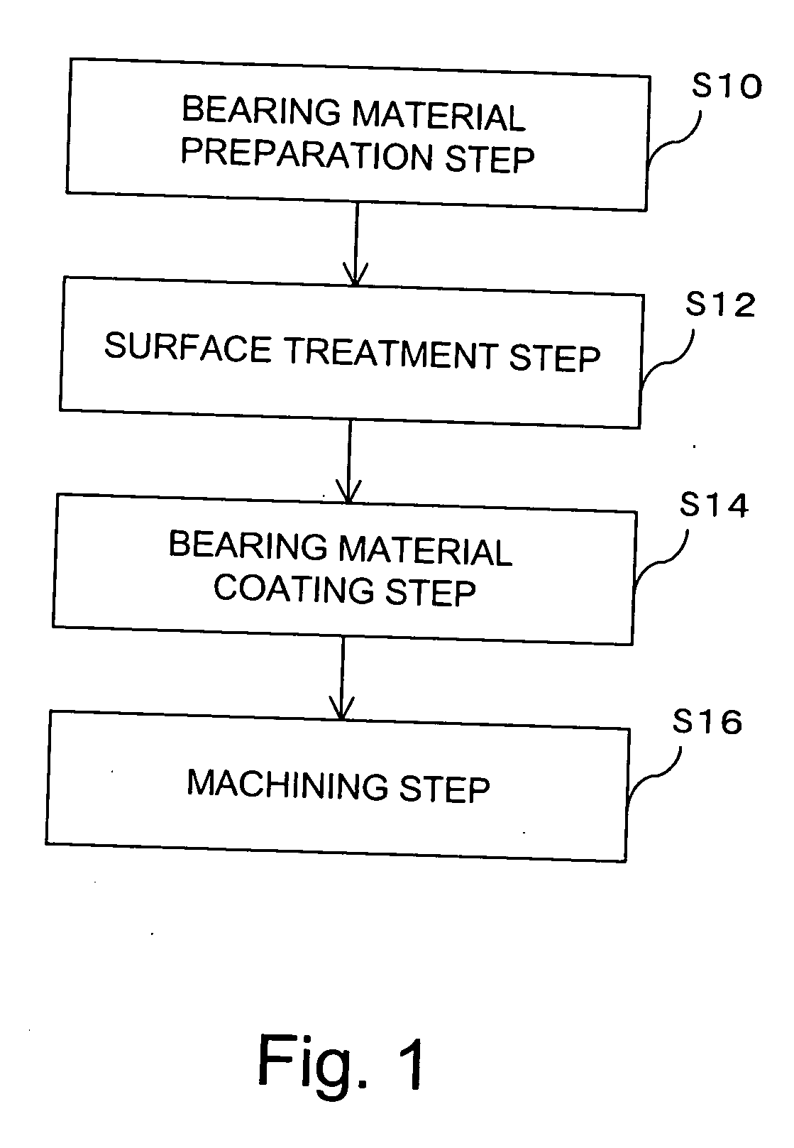
[0057] A Cu alloy powder containing Sn and an Fe—P powder used as a hard material were prepared in the bearing material preparation step (S10). Specifically, a Cu—Sn—Ag alloy powder containing 8 wt % of Sn and 1 wt % of Ag was used for the Sn containing Cu alloy powder. The Cu—Sn—Ag alloy powder was manufactured by the gas atomizing method using a nitrogen gas, and adjusted to be of a grain size of from 10 μm to 45 μm. The Fe—P powder was adjusted to be of a grain size of from 5 μm to 20 μm. Then, 95 wt % of the Cu—Sn—Ag alloy powder and 5 wt % of the Fe—P powder were mixed, and the resulting mixture was used as the bearing material.

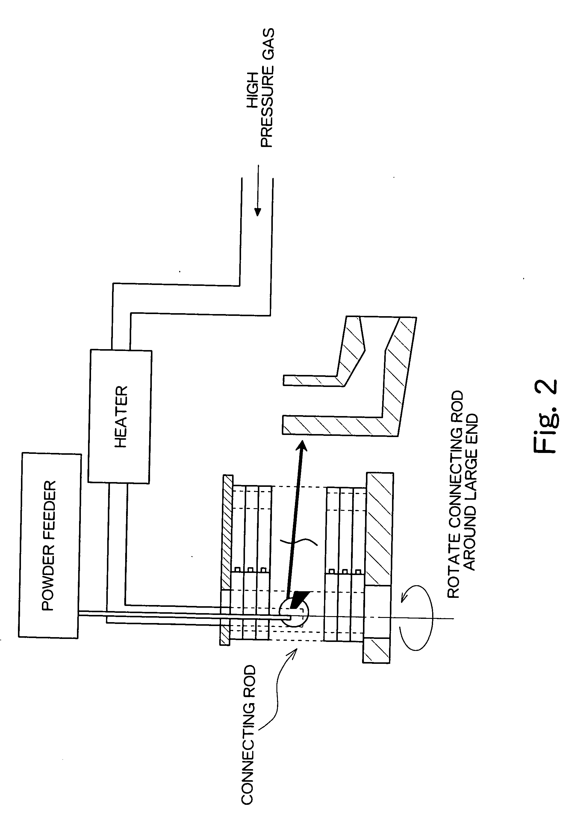
[0058] A molded connecting rod having an internal diameter of 48 mm at a large end thereof was used as the slide member. In the bearing material coating step (S14), the bearing material was coated on the sliding surface by means of the above-described cold gas dynamic spraying while rotating 12 molded connecting rods stacked on top of each other. The co...

example 2

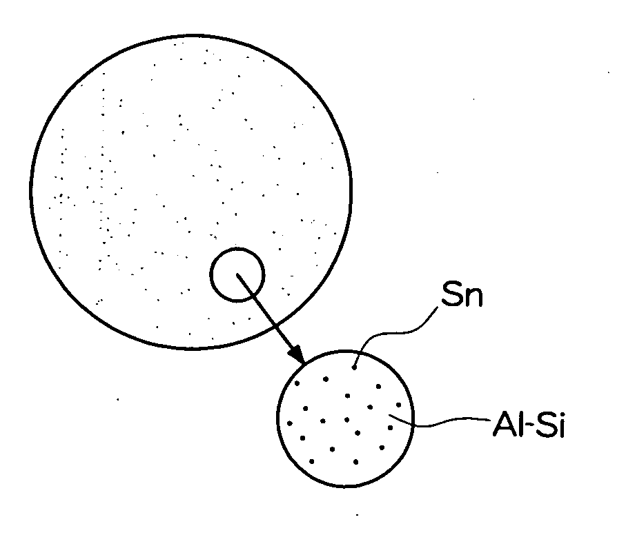
[0059] An Al alloy powder containing Sn and an Al2O3 powder used as a hard material were prepared in the bearing material preparation step (S10). Specifically, an Al—Sn alloy powder containing 12 wt % of Sn was used for the Sn containing Al alloy powder. The Al—Sn alloy powder was manufactured by the gas atomizing method using a nitrogen gas, and adjusted to be of a grain size of from 10 μm to 45 μm. The Al2O3 powder was adjusted to be of a grain size of from 2 μm to 5 μm. Then, 95 wt % of the Al—Sn alloy powder and 5 wt % of the Al2O3 powder were mixed, and the resulting mixture was used as the bearing material.

[0060] A molded connecting rod having an internal diameter of 48 mm at a large end thereof was used as the slide member. In the bearing material coating step (S14), the bearing material was coated on the sliding surface by means of the above-described cold gas dynamic spraying while rotating 12 molded connecting rods stacked on top of each other. The cold gas dynamic sprayi...

example 3

[0061] A fatigue test using dynamic load was conducted using a dummy connecting rod to evaluate fatigue performance of a bearing portion in the molded connecting rods experimentally manufactured in Examples 1 and 2. FIG. 5 shows an outline of a method for the fatigue test using dynamic load. In the fatigue test, a shaft which is the object to be fitted was inserted into the dummy connecting rod, and was rotated at a rotation speed of 3000 rpm. The dummy connecting rod, being the molded connecting rod, was moved up and down while the shaft was rotated, to thereby impart a predetermined bearing stress on the bearing portion. One rotation of the shaft was defined as one repetition. A load for vertically moving the dummy connecting rod was 5×10⁴N˜7×10⁴N, and the thickness of the dummy connecting rod was 17 mm. A material of the shaft, being the object to be fitted, was quenched S55C carbon steel for machine construction, and the shaft was formed so as to have a diameter of 42 mm. Furthe...


PUM

PropertyMeasurementUnit
particle sizeaaaaaaaaaa
velocityaaaaaaaaaa

Abstract

The present invention provides a bearing material coated slide member manufactured by coating a bearing material on a sliding surface of a slide member, and a method for manufacturing the same, in which the bearing material is composed of an Sn containing alloy powder, and is forced to impact on the sliding surface while being maintained in a solid phase, to thereby form a bearing material coated layer.

Description

[0001] The entire disclosure of Japanese Patent Application No. 2005-200378 including specification, claims, drawings and abstract is incorporated herein by reference in its entirety. BACKGROUND OF THE INVENTION [0002] 1. Field of the Invention [0003] The present invention relates to a method for manufacturing a bearing material coated slide member and to the bearing material coated slide member, and more particularly to a method for manufacturing a bearing material coated slide member in which a bearing material is coated on a sliding surface of a slide member and to the bearing material coated slide member manufactured by the method. [0004] 2. Description of the Related Art [0005] A sliding surface of a slide member, such as a connecting rod used for a vehicle engine, is provided with a bearing, such as a sleeve bearing, to reduce friction between the sliding surface and a shaft acting as a rotation axis, thereby enhancing lubricity to improve the sliding property of the sliding s...

Claims


Application Information

Patent Timeline
Patent Type & Authority Applications(United States)
IPC IPC(8): G01K5/66B22F3/26B32B15/00
CPCB22F2998/00Y10T428/12667C23C4/124C23C24/04F16C9/04F16C33/12F16C33/14C23C4/122Y10T428/12507F16C2204/22F16C2204/12Y10S384/912Y10S384/907Y10T428/12514Y10T428/1216B22F9/082F16C2204/20C23C4/129C23C4/126F16C2223/08F16C2223/80F16C2223/42F16C2220/60
Inventor MIYAMOTO, NORITAKAHIRANO, MASAKI
Owner TOYOTA JIDOSHA KK
Why Eureka
Try Eureka