Cutting method and apparatus and rib electrode for electric discharge machining

a cutting method and electric discharge technology, applied in the direction of electrical-based machining electrodes, manufacturing tools, other manufacturing equipment/tools, etc., can solve the problems of poor machining accuracy, difficult machining, difficult to machine with rotary cutting tools, etc., to improve machining efficiency and machining accuracy, reduce the interval of cutting edges, and improve the effect of machining efficiency and quality of finished surfaces

Inactive Publication Date: 2007-01-18
MAKINO MILLING MASCH CO LTD
View PDF29 Cites 12 Cited by
  • Summary
  • Abstract
  • Description
  • Claims
  • Application Information

AI Technical Summary

Benefits of technology

[0020] According to the present invention, as the shape of the cutting edge of the cutting tool is determined so as to be of a shape corresponding to the cross section of the rib portion to be machined and a cutting edge prepared to that shape is used, the rib portion can be machined simply by moving the cutting tool relative to the workpiece along the machining path extending in the longitudinal direction of the rib portion. As compared with the conventional cutting operation using the rotary cutting tool such as an end mill or a ball-end mill, the machining efficiency and the quality of the finished surface are higher. As the cutting edge of the cutting tool is prepared to the shape corresponding to the cross section of the rib portion to be machined, both side surfaces of the rib portion can be cut at one time with the cutting tool having a two-pronged cutting edge. In this case, the thin rib portion is machined while being supported on both sides thereof by the cutting edge. Therefore, the rib portion is not displaced or vibrated, thereby improving the machining efficiency and the machining accuracy. Also, as the shape of the cutting edge can be adjusted, the rib portions having various thickness or gradients can be machined by means of a single cutting tool apparatus. After the rib portion is roughly machined, the interval of the cutting edge can be reduced for finish machining. Therefore, the types of cutting tools to be prepared can be reduced. Further, as the base portion and the rib portion of the rib electrode are machined integrally with each other, the machining accuracy of the rib electrode as a whole is high. Also, as the base portion has the reference surface, the job of mounting the rib electrode on the electrode holder is facilitated.

Problems solved by technology

In this machining method, a groove of a rubber die or the like, which is difficult to machine with a rotary cutting tool, is cut using a formed spring-necked turning tool.
In the case where a thin rib electrode is generated by cutting each side thereof at a time with a rotary cutting tool such as an end mill or a ball-end mill, the deflection or vibration of the rib portion of the workpiece results in a poor machining accuracy and makes the machining difficult.
Especially, when a rib electrode having a very high aspect ratio, i.e. the ratio of height to thickness of the rib, is cut with an end mill or a ball-end mill, the resulting deflection or vibration leads to the problem that the cutting load cannot be imposed and the required cutting accuracy is not attained.
Also, it is difficult to machine a thin tabular rib electrode for electric charge machining with high accuracy and mount it accurately on an electrode holder.
This poses a problem that considerable time is required for the machining and mounting job.

Method used


Image

  • Cutting method and apparatus and rib electrode for electric discharge machining
  • Cutting method and apparatus and rib electrode for electric discharge machining
  • Cutting method and apparatus and rib electrode for electric discharge machining

Examples


Embodiment Construction

[0026] Preferred embodiments of the present invention will be described below with reference to the accompanying drawings.

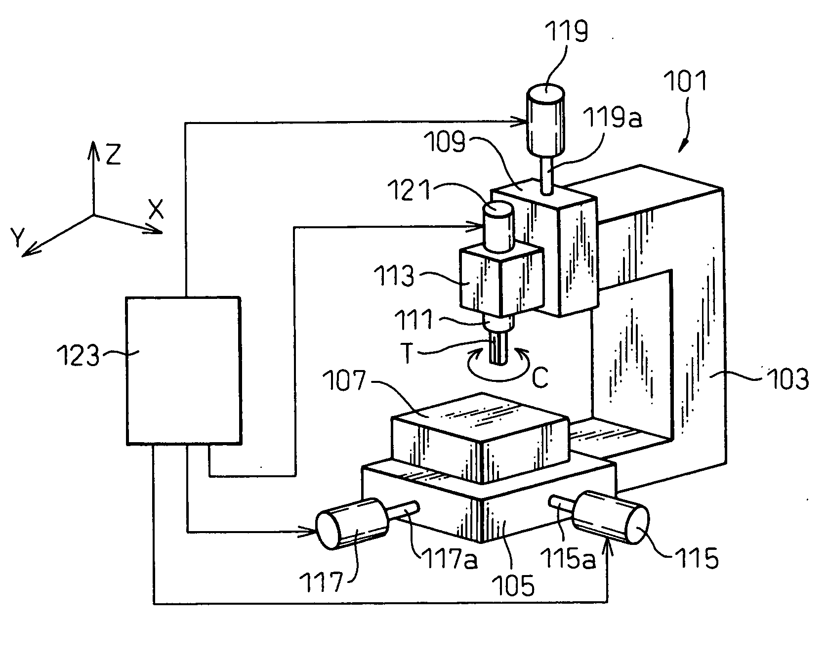
[0027] First, a cutting apparatus according to an embodiment of the present invention will be described with reference to FIG. 3. The cutting apparatus 101 includes, as main components, a column 103, an X-Y feed mechanism 105 located on the front side of the lower portion of the column 103, a table 107 located on the X-Y feed mechanism 105 for fixing a workpiece, a Z-axis feed mechanism 109 located on the front side of the upper portion of the column 103, and a spindle head 113 mounted on the Z-axis feed mechanism 109 for rotatably supporting a spindle 111.

[0028] The X-Y feed mechanism 105 includes X-axis and Y-axis feed shafts 115a, 117a constituted by ball screws extending in directions along X-axis and Y-axis orthogonal to each other in a horizontal plane, nuts (not shown) located on a lower surface of a table 107 and adapted to engage with the X-axis and Y-...


PUM

PropertyMeasurementUnit
thicknessaaaaaaaaaa
thicknessaaaaaaaaaa
thicknessaaaaaaaaaa

Abstract

An object of the present invention is to provide a cutting method and apparatus and a rib electrode for electric discharge machining which can cut a rib portion of a workpiece efficiently and accurately. For this purpose, a cutting tool 11 having cutting edges 23a, 23b extending in parallel or extending along two straight lines diverging toward the forward end in the same plane is prepared. The cutting tool 11 is arranged with respect to a workpiece W such that the two cutting edges 23a, 23b engage with the two opposed side surfaces of the rib portion R of the workpiece W. The cutting tool 11 is moved relative to the workpiece W along a desired machining path, to thereby cut the two side surfaces of the rib portion R of the workpiece W at one time.

Description

TECHNICAL FIELD [0001] The present invention relates to a cutting method, a cutting apparatus and a cutting tool apparatus suitable for machining the rib portion of a workpiece, and to a rib electrode for electric discharge machining machined by the cutting tool apparatus. BACKGROUND ART [0002] A die used for plastic molding or the like is typically cut by an end mill or a ball-end mill. A plastic molded product is often provided with a thin rib or ribs for reinforcement. The rib of the plastic molded product is typically formed as a thin tabular protrusion member having a taper. In the case where the molded product has a thin rib or ribs, the die portion corresponding to the rib is machined by electric discharge using a rib electrode. In the prior art, the rib electrode used for electric discharge machining is fabricated by cutting with a rotary cutting tool such as an end mill or a ball-end mill or by grinding with a grinding wheel. [0003] A method of cutting a workpiece with a no...

Claims


Application Information

Patent Timeline
Patent Type & Authority Applications(United States)
IPC IPC(8): B23P23/00B23B5/16B23D5/02B23D13/04B23H1/04B23H9/00B23H9/10
CPCB23B5/166B23D5/02B23D13/04B23H9/00Y10T409/303808Y10T29/49998Y10T409/50082Y10T409/509348B23H9/10B23D1/08B23D17/04
Inventor KOSUGE, YASUHISAISHIDA, NOBUYA
Owner MAKINO MILLING MASCH CO LTD
Why Eureka
Try Eureka