Component for insert casting, cylinder block, and method for manufacturing cylinder liner
a technology of cylinder block and insert casting, which is applied in the direction of manufacturing tools, machines/engines, superimposed coating processes, etc., can solve the problems of metal particles, which have been melted at a high temperature, colliding with the cylinder block, and not improving the cooling performance to a satisfactory level, and achieves high thermal conductivity.
- Summary
- Abstract
- Description
- Claims
- Application Information
AI Technical Summary
Benefits of technology
Problems solved by technology
Method used
Image

Examples
first embodiment
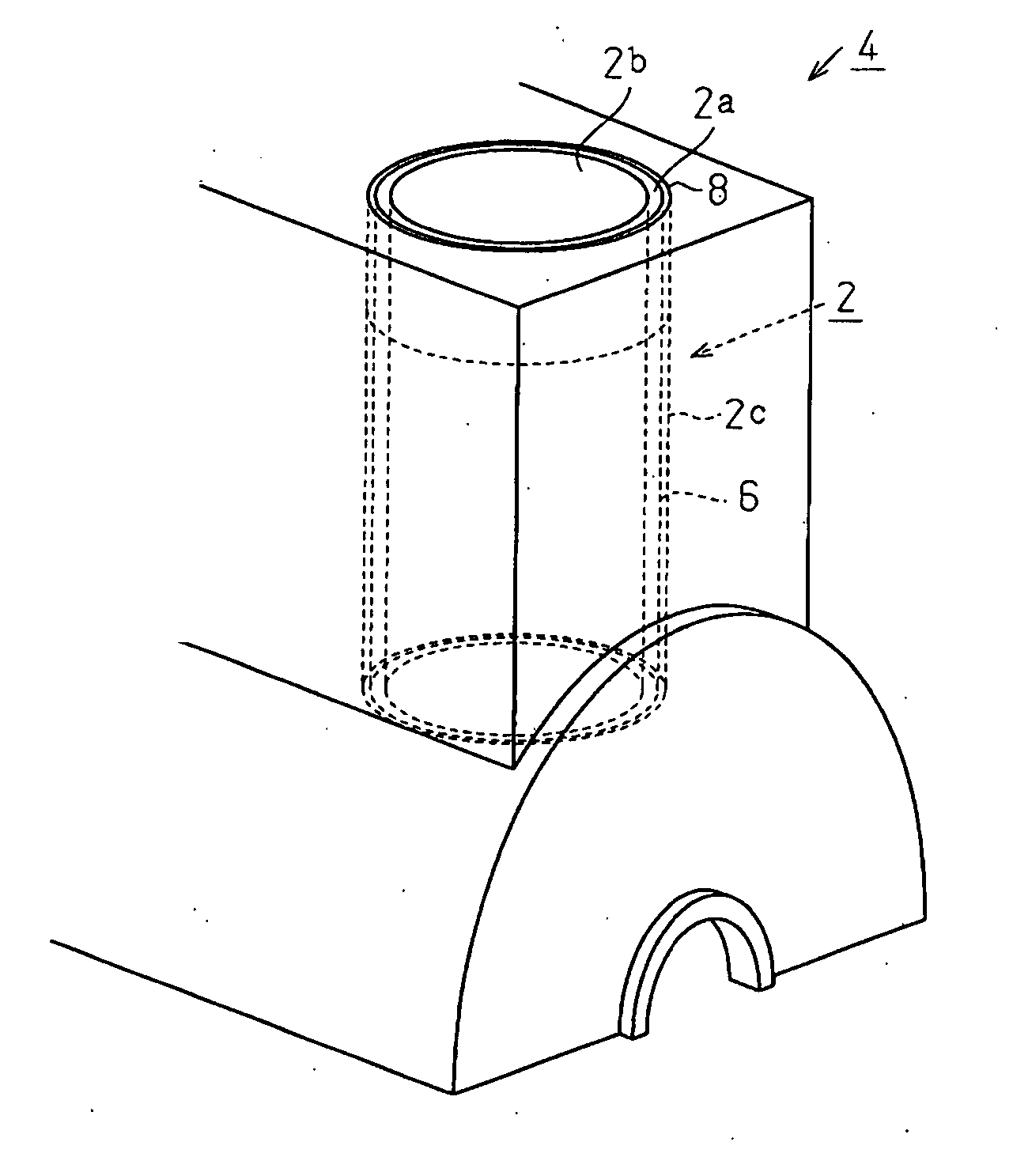
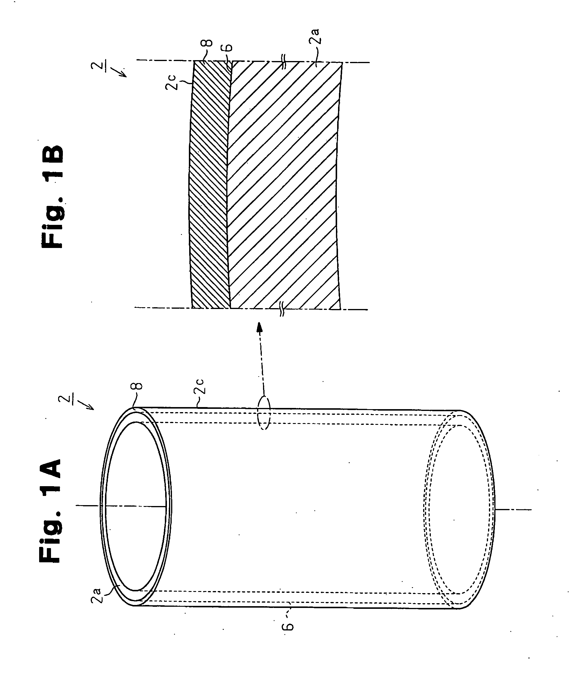
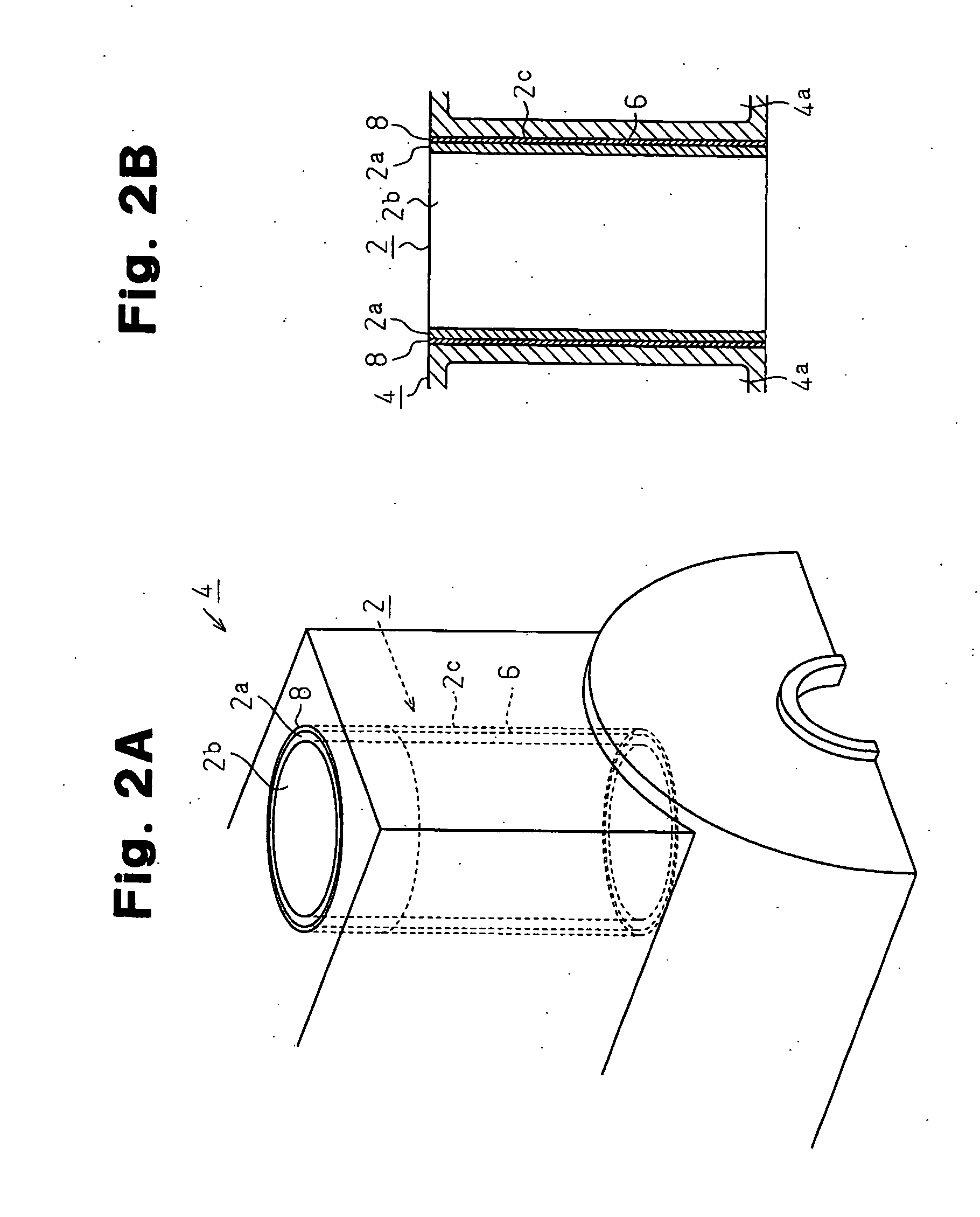
[0032] A first embodiment is shown in FIGS. 1A, 1B, 2A, and 2B. FIG. 1A is a perspective view a cylinder liner 2 according to the present invention. FIG. 1B is a partially enlarged cross-sectional view of the cylinder liner 2. FIG. 2A is a partially perspective view of a cylinder block 4 in which the cylinder liner 2 is enveloped through insert casting. FIG. 2B is a partially enlarged cross-sectional view of the cylinder block 4. A water jacket 4a is formed about the cylinder liner 2, which is enveloped in the cylinder block 4.
2>
[0033] A body 2a of the cylinder liner 2 shown in FIGS. 1A and 1B is a cylindrical body made of cast iron. The cylinder liner 2 is formed by forming a metal coating layer 8 on an outer circumferential surface 6 of the cylinder liner body 2a (hereafter referred to as outer circumferential surface). The metal coating layer 8 metallurgically bonds the cylinder liner 2 with the cylinder block 4 during casting.
[0034] Taking the wear resistance, the seizure resi...
second embodiment
12>
[0056]FIG. 4 is a partially cross-sectional view of a cylinder liner according to a second embodiment. Although a body 12a of the cylinder liner 12 is made of cast iron having the same composition as that of the first embodiment, a plurality of projections 17 each having a constricted shape are integrally formed on an outer circumferential surface 16. Each projection 17 is formed in the following manner.
[0057] (1) Each projection 17 has the narrowest section (constriction 17c) in middle portion between a proximal end 17a and a distal end 17b.
[0058] (2) Each projection 17 is flared from the constriction 17c toward the proximal end 17a and toward the distal end 17b.
[0059] (3) Each projection 17 has a substantially flat top surface 17d at the distal end 17b. The top surface 17d is the outermost surface in the radial direction of the cylinder liner body 12a.
[0060] (4) A substantially flat surface (base surface 17e) is formed between the projections 17.
[0061] After the outer circ...
third embodiment
[0107] In a third embodiment, a cylinder liner body 22a, which is the same as the cylinder liner body of the first embodiment is used. A metal coating layer 28 is formed on the cylinder liner body 22a with a low melting point metal powder material by using a cold spraying apparatus, thereby producing a cylinder liner 22.
[0108] The low melting point metal material may be zinc, a zinc alloy, tin, a tin alloy, lead, a lead alloy, antimony, or an antimony alloy.
[0109] Like the metal coating layer of the first embodiment, the metal coating layer 28 formed by cold spraying contains few oxide films and oxide layers on the surface and in the interior.
[0110] As shown in FIG. 10, the cylinder liner 22 is enveloped in a molten metal 30 of a block material as in the first embodiment, thereby casting a cylinder block. During casting, since the metal coating layer 28 has a melting point lower than that of the block material (aluminum or an aluminum alloy) forming the molten metal 30, the molte...
PUM
| Property | Measurement | Unit |
|---|---|---|
| Length | aaaaa | aaaaa |
| Length | aaaaa | aaaaa |
| Fraction | aaaaa | aaaaa |
Abstract
Description
Claims
Application Information
 - R&D
- Intellectual Property
- Life Sciences
- Materials
- Tech Scout
- Unparalleled Data Quality
- Higher Quality Content
- 60% Fewer Hallucinations
Browse by: Latest US Patents, China's latest patents, Technical Efficacy Thesaurus, Application Domain, Technology Topic, Popular Technical Reports.
© 2025 PatSnap. All rights reserved.Legal|Privacy policy|Modern Slavery Act Transparency Statement|Sitemap|About US| Contact US: help@patsnap.com