
Flow restrictor and system for delivering a flow of liquid in a microcapillary

a flow restrictor and microcapillary technology, applied in mechanical apparatus, process and machine control, instruments, etc., can solve the problems of unpredictability, lack of yield and predictability, and the occurrence of bubble fragmentation in microcapillary flow restrictors, so as to reduce the tendency to bubble fragmentation and increase the yield of devices

Active Publication Date: 2007-01-18
CEQUR SA
View PDF3 Cites 3 Cited by
  • Summary
  • Abstract
  • Description
  • Claims
  • Application Information

AI Technical Summary

Benefits of technology

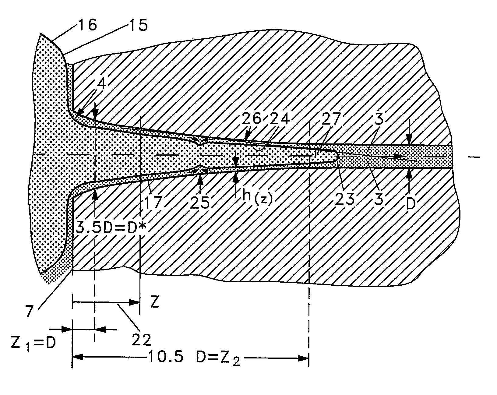
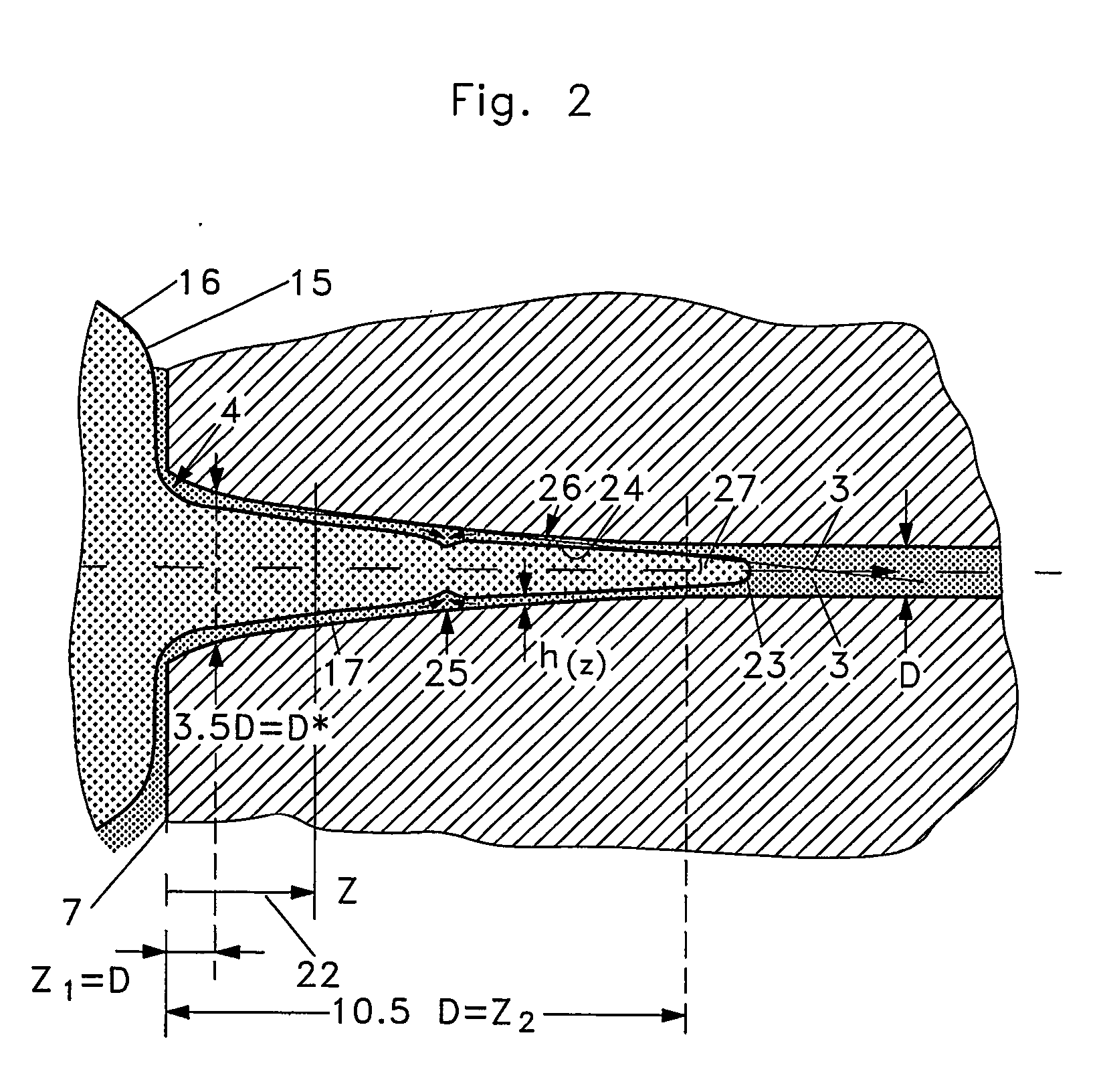
The present invention provides a flow restrictor structure that has less tendency towards bubble fragmentation, is more predictable in its bubble fragmentation behavior, and provides a higher yield of usable devices than commonly known microcapillary flow restrictors. This is achieved by widening the flow channel at the inlet in a smooth and gradual manner, which reduces the tendency towards bubble fragmentation and increases the yield of devices that operate well.

Problems solved by technology

A problem with capillaries of very small internal diameter (microcapillaries) is that bubbles of gas in the liquid may have a serious impact on the pressure difference or pressure drop required to drive a given flow rate through the capillary, and in the worst case bubbles may lead to an effective blocking of the capillary.
Unfortunately, however, experience shows that the occurrence of bubble fragmentation in microcapillary flow restrictors is not predictable.
There is a lack of yield and a lack of predictability.
Both are major obstacles in the industrial use of microcapillary flow restrictors, for example in mass fabrication of medical infusion devices.

Method used


Image

  • Flow restrictor and system for delivering a flow of liquid in a microcapillary
  • Flow restrictor and system for delivering a flow of liquid in a microcapillary
  • Flow restrictor and system for delivering a flow of liquid in a microcapillary

Examples


Embodiment Construction

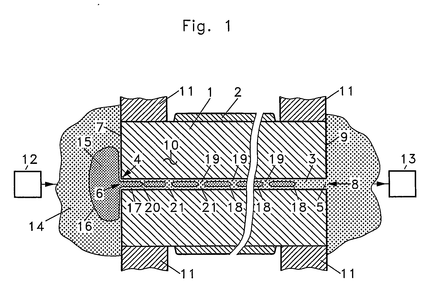
[0016]FIG. 1 shows a capillary flow restrictor 10 made by cutting off a length of microcapillary which is commercially available from various vendors for use in the field of chemical analysis (gas chromatography, capillary electrophoresis etc).

[0017] The device 10 is an elongated tube whose wall 1 is made from fused silica (quartz glass) with an outer cladding 2 of polyimide. The wall 1 surrounds a flow channel 3 of circular or rectangular (for example, square) cross-section which extends from an inlet 4 to an outlet 5. At the inlet, the flow channel 3 forms an inlet opening 6 in an inlet face 7 of the flow restrictor, and at the outlet it forms an outlet opening 8 in an outlet face 9 of the flow restrictor. Depending on how the device was cut off, the inlet face 7 and the outlet face 9 of the device may be smooth (from abrasive cutting) as shown at 7 or slightly rough (from scoring and breaking) as shown at 9.

[0018] The flow restrictor 10 is mounted in a flow system for deliverin...


PUM


Abstract

The present invention relates to apparatus for delivering a controlled or restricted flow of liquid and limiting bubble fragmentation at the inlet. This is achieved in flow restrictor with a flow channel having over most of its length a substantially constant, minimum hydraulic diameter D=4A / W wherein A is the minimum local cross-sectional area of the channel and W is the minimum local wetting perimeter of the channel, by smoothly widening the channel at its inlet such that: at distances z from the inlet face with 0<z<z1, the channel has a hydraulic diameter Dz≧k*D wherein k≧1.3; at distances z from the inlet face with z1<z<z2, the channel has a hydraulic diameter Dz with k*D≧Dz≧D; and at distances z from the inlet face with z2<z, the channel has a hydraulic diameter Dz with Dz≦1.02D, except possibly for a similar widening of the channel at the outlet. It has been found that widening the flow channel at the inlet, such that its diameter increases smoothly and gradually, and preferably by a factor of at least 1.3 over a length of at least 3 channel diameters, significantly reduces the tendency towards bubble fragmentation in microcapillary flow restrictors, and also substantially increases the yield of devices which operate well.

Description

CROSS REFERENCE TO RELATED APPLICATIONS [0001] This application is entitled to the benefit of and incorporates by reference essential subject matter disclosed in International Patent Application No. PCT / DK2004 / 000587 filed on Sep. 4, 2004 and Danish Patent Application No. PA 2003 01301 filed Sep. 10, 2003. FIELD OF THE INVENTION [0002] The present invention relates to apparatus for delivering a controlled or restricted flow of liquid. An example of such apparatus is an infusion pump for delivering a controlled flow of medication to a patient during a certain period of time which can be a number of days. Other applications might be envisaged in the chemical or biotechnology fields. BACKGROUND OF THE INVENTION [0003] In medical infusion, the flow typically needs to be restricted to rather low rates, such as, for example, 1000 microlitres per hour. Delivery of liquids at flow rates of a few millilitres per hour or less may be realized by connecting a source of pressurized liquid to a c...

Claims


Application Information

Patent Timeline
Patent Type & Authority Applications(United States)
IPC IPC(8): F16K47/00A61M5/14A61M5/142F15C5/00F16K99/00
CPCA61M5/141A61M5/14276A61M5/16877F15C5/00F16K2099/0086F16K99/0017F16K99/0026F16K99/0057F16K99/0001
Inventor GRAVESEN, PETERMANSCHER, MARTINRASMUSSEN, PER BRANDT
Owner CEQUR SA
Learn More