
Optical source with ultra-low relative intensity noise (RIN)

a laser source and relative intensity noise technology, applied in the field of laser sources, can solve the problems of limiting the dynamic range at the high power side, nonlinear spurious, and limiting the distortion of the communication link, and achieve the effect of reducing the resulting relative intensity noise of the ligh

Inactive Publication Date: 2007-01-18
II VI DELAWARE INC
View PDF76 Cites 12 Cited by
  • Summary
  • Abstract
  • Description
  • Claims
  • Application Information

AI Technical Summary

Benefits of technology

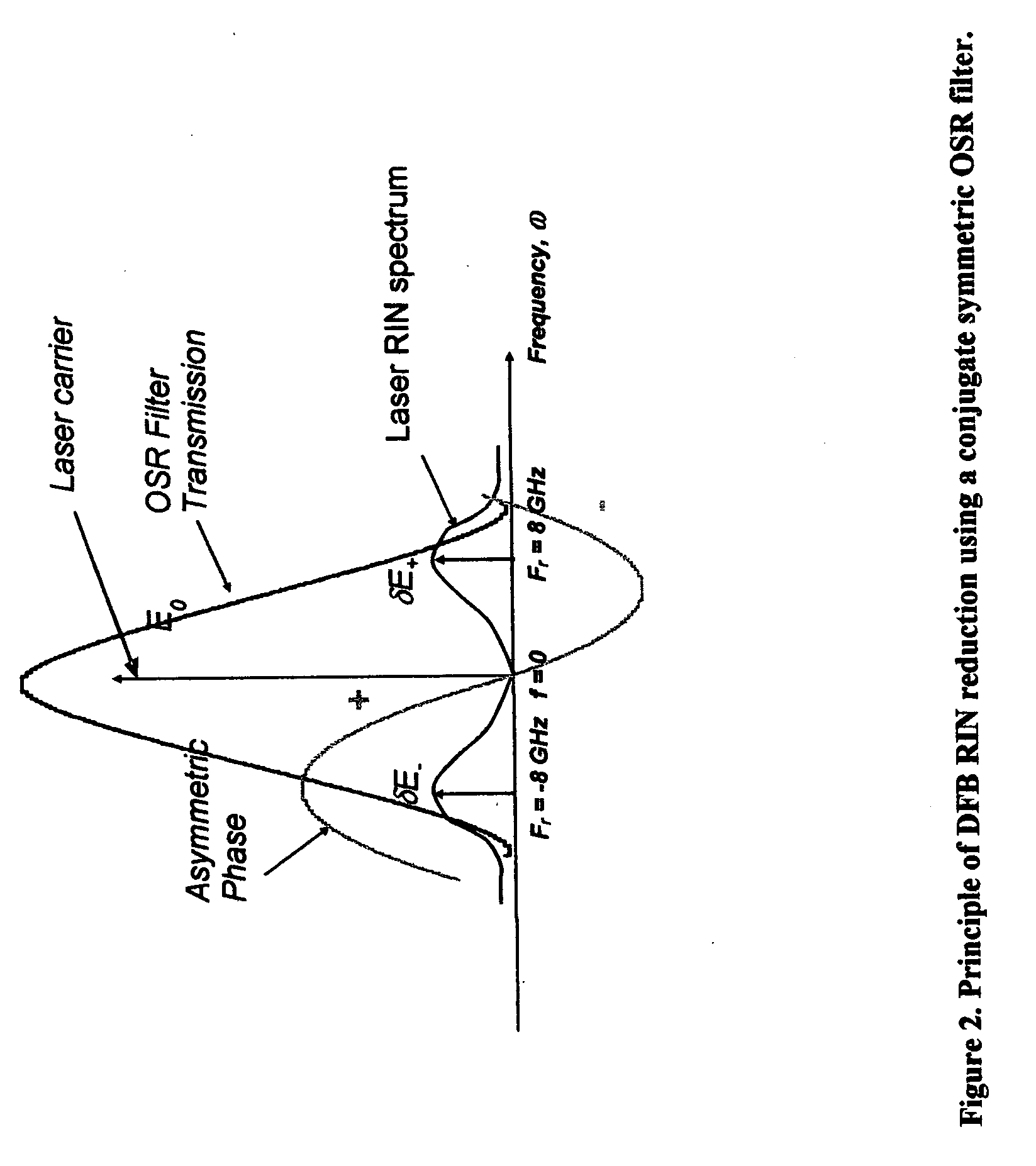
[0016] wherein the transmission function of the filter is chosen, and the frequency dependent relative intensity noise spectrum of the laser is adjusted, to reduce the resulting relative intensity noise of the light at the output of the filter over a range of frequencies by causing the relative intensity noise spectrum of the laser to occur at frequencies for which the filter has substantial loss.

Problems solved by technology

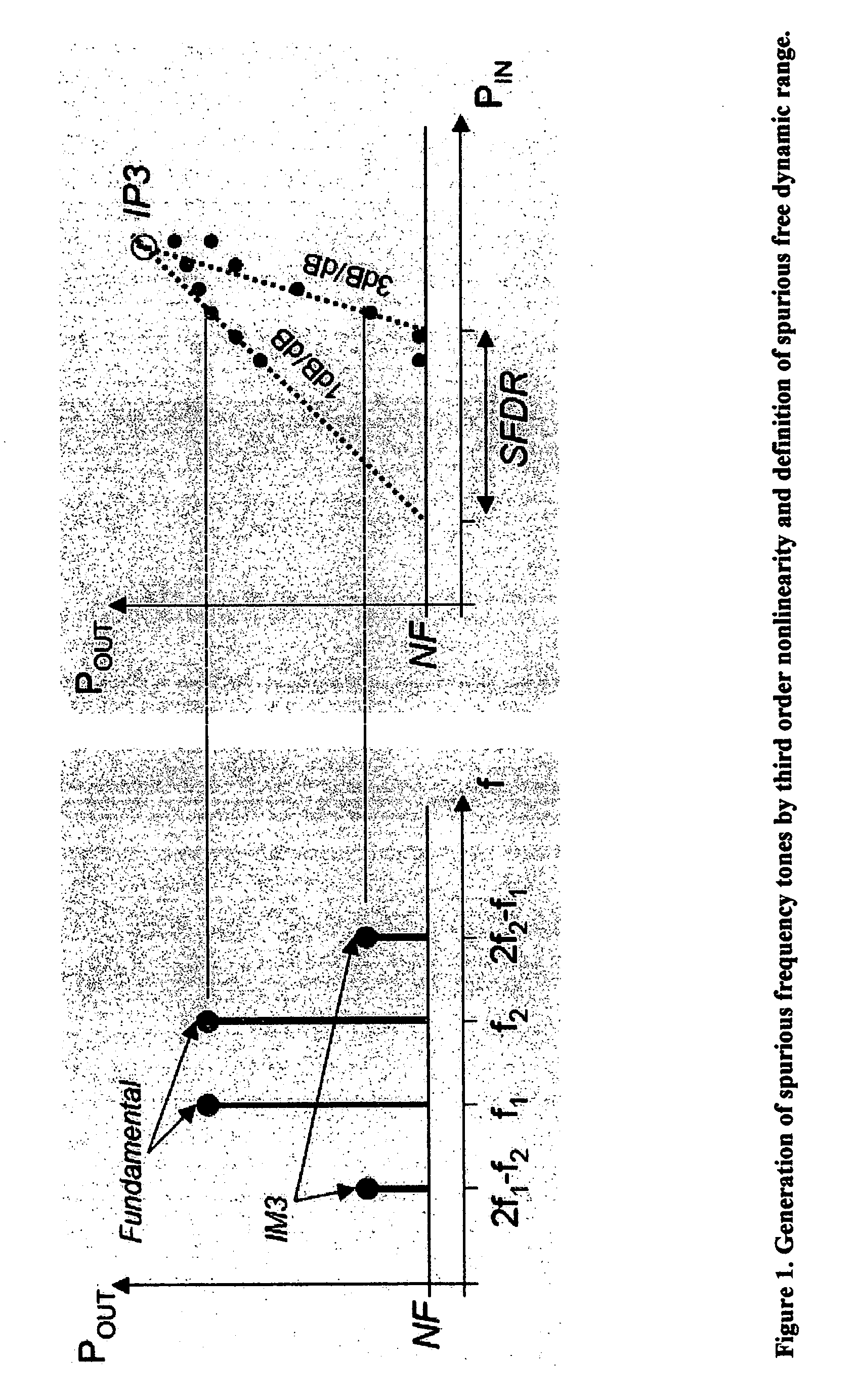
Therefore, the communication link's distortion is typically limited by third-order nonlinearity dictated by the approximately sinusoidal transfer function of the modulator.
These nonlinear spurious tones become significant at high input RF powers to the modulator and limit the dynamic range at the high power side.
The dynamic range at the low power levels is limited by the noise of the systems.
However, such solid state lasers are typically large and have high power consumption.
In other applications, the semiconductor RIN is high enough to present significant problems.
However, as the bandwidth (BW) requirements for analog communication increases, higher frequency RF carriers are needed, requiring compact lasers with low RIN over a wide band of frequencies in the multi-GHz range.

Method used


Image

  • Optical source with ultra-low relative intensity noise (RIN)
  • Optical source with ultra-low relative intensity noise (RIN)
  • Optical source with ultra-low relative intensity noise (RIN)

Examples


Embodiment Construction

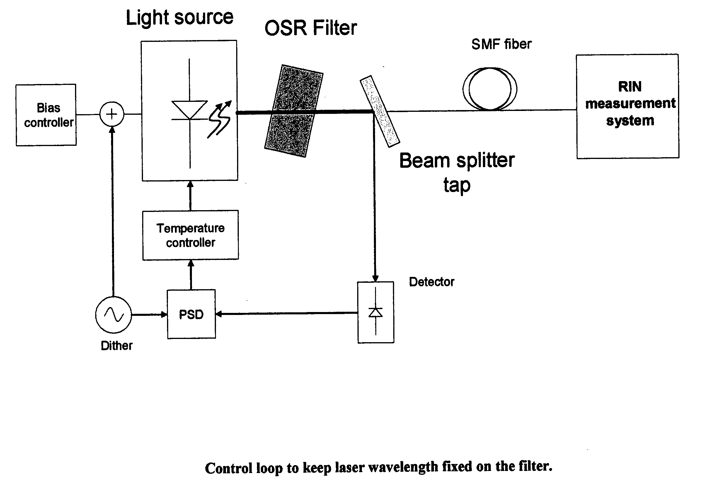
[0025] In a preferred embodiment of the present invention, the RIN-reduced CW laser comprises a laser (e.g., a standard high power DFB laser) followed by a passive optical filter, which may be referred to as an optical spectrum reshaper (OSR). The OSR can be made from a variety of low loss materials such as silica or transparent thin films, and can be made to be small, occupying ˜2 mm, making for a compact low RIN source. The OSR can be a variety of filters such as a Bragg grating filter, a multi-cavity waveguide ring resonator filter, a thin film filter, etc.

[0026]FIG. 2 shows the principle of operation of RIN reduction. The RIN of a DFB laser has a damped resonant frequency response. The laser RIN can be near the Shot noise limit at very low frequencies and increases to a peak value at the resonant frequency of the laser. The resulting optical spectrum resembles a double sideband modulated optical carrier. The RF noise in the detector is therefore generated by the sum of the beat...


PUM


Abstract

Apparatus for the generation of ultra-low noise light comprising: a laser generating light at a central frequency and having a frequency dependent relative intensity noise spectrum; and an optical filter having a substantially conjugate symmetric transfer function; wherein the center frequency of the light generated by the laser is substantially aligned with the peak transmission frequency of the filter; and wherein the transmission function of the filter is chosen, and the frequency dependent relative intensity noise spectrum of the laser is adjusted, to reduce the resulting relative intensity noise of the light at the output of the filter over a range of frequencies by causing the relative intensity noise spectrum of the laser to occur at frequencies for which the filter has substantial loss.

Description

REFERENCE TO PENDING PRIOR PATENT APPLICATIONS [0001] This patent application claims benefit of pending prior U.S. Provisional Patent Application Ser. No. 60 / 678,014, filed May 05, 2005 by Daniel Mahgerefteh et al. for ULTRA LOW RELATIVE INTENSITY NOISE LASER MODULE (Attorney Docket No. TAYE-55 PROV). [0002] The above-identified patent application is hereby incorporated herein by reference.FIELD OF THE INVENTION [0003] This invention relates to laser sources in general, and more particularly to low noise laser sources for high dynamic range analog communication systems. BACKGROUND OF THE INVENTION [0004] Analog fiber optic communication requires lasers with low relative intensity noise (RIN) and high power to increase their linear dynamic range. Analog fiber links typically comprise a high-power, continuous-wave (CW) laser diode and an externally modulated Lithium Niobate (LiNbO3) modulator, which is used to modulate the optical carrier with a radio frequency (RF) signal such as a v...

Claims


Application Information

Patent Timeline
IPC IPC(8): G01J1/32H01J40/14
CPCG01J2003/1213H01S2301/02H01S5/0687H01S5/0078
Inventor MAHGEREFTEH, DANIELMATSUI, YASUHIROTAYEBATI, PARVIZ
Owner II VI DELAWARE INC
Learn More