Eureka AIR delivers breakthrough ideas for toughest innovation challenges, trusted by R&D personnel around the world.

Lubricious or/and wettable or/and Anti-thrombin elastomeric gland materials in luer activated devices

a technology of lubricating or wettable or antithrombin elastomeric glands and activated devices, which is applied in the direction of mechanical devices, other medical devices, couplings, etc., can solve the problems of gland sticking down, valve failure, gland sticking down, etc., and achieve the effect of increasing the wettability of the gland and preventing clotting

Inactive Publication Date: 2007-01-18
BAXTER INT INC +1
View PDF17 Cites 26 Cited by
  • Summary
  • Abstract
  • Description
  • Claims
  • Application Information

AI Technical Summary

Benefits of technology

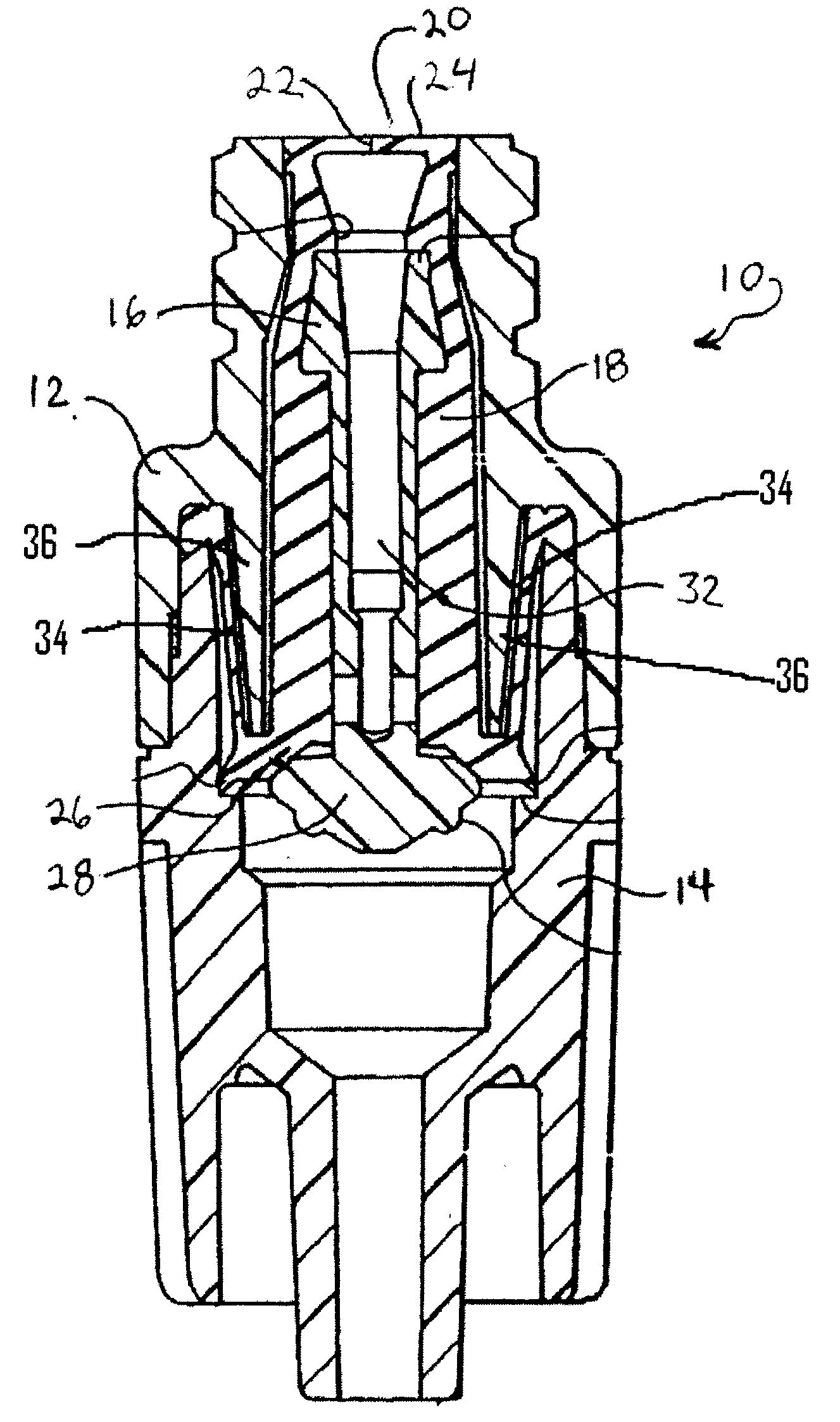
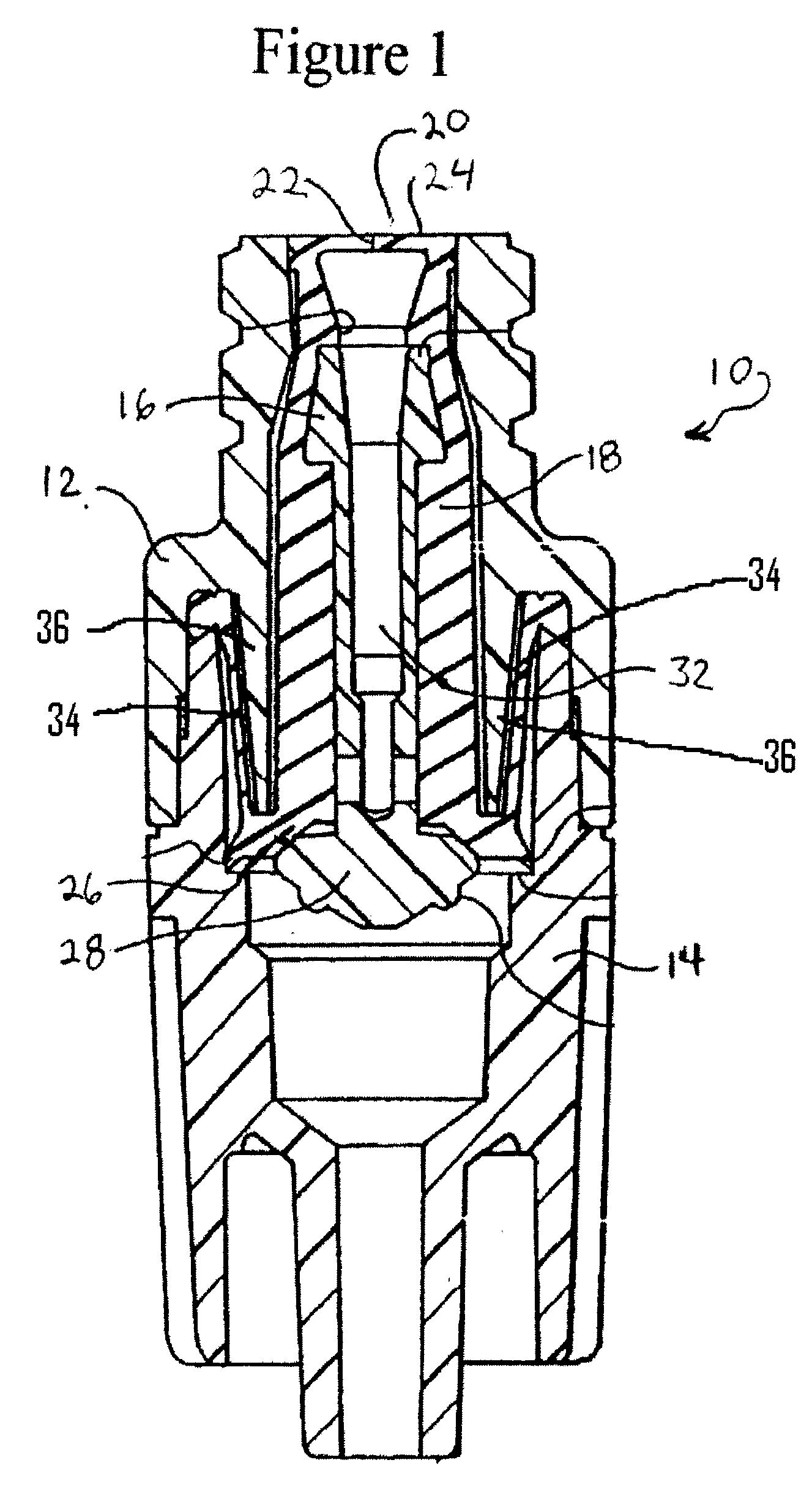
[0011] In one aspect of the present invention, a unique lubricant and / or wetting agent and / or anti-clotting agent is incorporated into an elastomeric gland of a Luer Activated Device (LAD) during raw material formulation, calendar blending / molding / curing. Such agent delivers surface lubricity and avoid slit plane re-knitting or gland web induced valve stick down and / or to increase wettability of the gland and / or to prevent clotting in the fluid path and interstitial spaces.

Problems solved by technology

In addition, the lubricant may act as a shield or coating which prevents slit or orifice re-knit, i.e. knitting shut, such that the slit or orifice doesn't open properly upon insertion of the luer tip.
Too much or too little application of lubricant can interfere with valve operation during use and may result in valve failure.
In addition, if the manufacturing process does not adequately apply or incorrectly applies the lubricant, re-knit may occur resulting in the slit failing to open on first use, the gland may stick down and fail to recover after actuation or the slit may later reseal and / or re-knit.
The hydrophobic nature of the gland also occasionally prevents adequate priming of the LAD.
The natural tendency of blood to clot can result in blockage of the flow path in LADs.

Method used


Image

  • Lubricious or/and wettable or/and Anti-thrombin elastomeric gland materials in luer activated devices
  • Lubricious or/and wettable or/and Anti-thrombin elastomeric gland materials in luer activated devices

Examples


example 1

[0039] In order to determine the functional attributes of the additive enhanced glands, a number of plaques of an elastomeric substrate typically used in making glands of LADs were made incorporating one or more additives along with a control having no additive.

[0040] The following table identifies the additives and testing performed:

Testing# ofC.O.FWettingBloodTensile bar% byplaquesvs.contactClottingtesting afterMaterialMix #Additivesweightto makeTimeangleTendencygammare-knit1No Additives / Control0.05XXXXXGroup2FL-100 fluorosilicone3.04XXX(100 cs)3DC550 phenyl silicone3.04XXX(125 cs)4MED 400 fluorosilicone1.02XX(1000 cs)5MED 400 fluorosilicone3.04XXX(1000 cs)6MED 400 fluorosilicone5.04XXX(1000 cs)7L-77 polysiloxane1.02Xpolyether copolymer (20 cs)8L-77 polysiloxane3.05XXXXpolyether copolymer (20 cs)9DC5324 polysiloxane1.02Xpolyether copolymer(350 cs)10DC5324 polysiloxane3.05XXXXpolyether copolymer(350 cs)11DC193 polysiloxane1.02Xpolyether copolymer(335 cs)12DC193 polysiloxane3.05X...

example 2

[0054] Some of the mixes of Example 1, specifically mixes 1-7, 16 and 17 were also tested to determine the effect of the lubricant additive on molecular cross-linking or re-knit of the silicone substrate.

[0055] For each mix tested, six rectangles were cut from the plaque with each rectangle measuring 3 inch×1 inch. Two of the rectangular samples were stacked together, so that a double-thick 3 inch×1 inch sample is formed. Wax paper was placed between the last 1 inch×1 inch end of the joined double-thick rectangle, so that only two-thirds of the area of each sample was in contact with each other. This was repeated for all n=6 rectangles in each group, so that n=3 samples were created for each group.

[0056] These samples were then placed into a fixture that helped to ensure a constant compressive force through sterilization. This fixture cannot contain any metal due to the gamma irradiation processing. This force should be about 5 psi, or 15 pounds per sample, distributed as evenly a...

example 3

[0060] Several of mixes of Example 1 were tested to determine the presence and / or extent of the wetting agent on the surface of the substrate. Contact angle wetting test was performed on mixes 1, 7-12, 16 and 17. Water droplet contact angles were measured using an AST VCA Optima contact angle goniometer. Five droplets were measured in three locations on the test plaque for each mixture. Each plaque was divided into nine symmetric sections resembling a tic-tac-toe grid and the top right most, center, and bottom left most sections were used as the test locations.

[0061] Five droplets, each having a volume of 2.0 ul, were dispensed linearly across the top half of each section. A measurement was taken after the each droplet was deposited with a short time lag to ensure no droplet movement. The measurements were repeated after a minimum of 24 hours of open exposure in a laboratory hood.

[0062] The results of the water droplet contact angle testing is shown on the following table:

Contac...


PUM


Abstract

An elastomeric gland is provided for a luer activating device (LAD). and comprises a unique lubricant and / or wetting agent and / or anti-clotting agent incorporated into the elastomer gland during raw material formulation, calendar blending / molding / curing to deliver the surface lubricity and / or wettability and / or avoid slit plane re-knitting and / or gland induced valve stick down of such devices Functional additive chemistries are selected in terms of generated functional performance level, thermal stability against processing, molecular migratability, molecular weight and elastomer substrate of interest. These additives could include lubricants like chemically modified silicone oils and / or wetting agents like silicone-based surfactant. Elastomer gland with wetting agent would ease fluid path priming and minimize micro air bubble adherence to gland surface. Additives may also include anti-clotting agents intended to reduce potential for clot formation within the fluid path and interstitial space of the valve during blood sampling and infusion.

Description

[0001] This application claims the benefit of U.S. Provisional Application Ser. No. 60 / 699,048 filed on Jul. 13, 2005BACKGROUND OF THE INVENTION [0002] Luer activated devices or LADs are designed to provide needleless aseptic access to medical fluid flow systems such as intravenous fluid administration sets or lines typically used in healthcare. LADs eliminate the need for “sharp” needles or blunt plastic cannula of specialized shape. Many of these LADs utilize elastomeric boots or glands which are displaced or deformed in some manner when a standard male luer tip is inserted into the device. This displacement or deformation will generally open a flow path through the device. In some designs, the gland will operate in conjunction with other components of the device to establish this flow path. After the luer tip is removed, the gland recovers to shut off the flow path. [0003] In many LAD designs the flow path is established by the opening of a pre-formed slit or orifice in the gland...

Claims


Application Information

Patent Timeline
IPC IPC(8): F16L37/28
CPCA61M39/26F16L37/28F16K1/12A61M2039/0036
Inventor LEE, YANN-PERDESECKI, VINCE
Owner BAXTER INT INC
Why Eureka
Eureka Blog
Learn More