
Manufacturing apparatus for oriented film, liquid crystal device and electronic device

Inactive Publication Date: 2007-01-18
SEIKO EPSON CORP
View PDF19 Cites 4 Cited by
  • Summary
  • Abstract
  • Description
  • Claims
  • Application Information

AI Technical Summary

Benefits of technology

[0030] According to this manufacturing apparatus, it is possible to remove the oriented film material adhered to the shielding plate by the cleaning section when maintenance for the apparatus is performed, while also maintaining the inside of the film formation chamber in a vacuum state.
[0049] Thus, since the electronic device includes the liquid crystal device having desirable qualities and improved productivity, the electronic device also has desirable qualities and improved productivity.

Problems solved by technology

However, when a liquid crystal device fitted with such an organic oriented film is adopted as the photo-modulation section of a projector, there is concern that the oriented film will gradually degrade due to strong light radiated from a light source or heat.
There is further concern that the orientation control function of liquid crystal molecules is reduced and the display quality of the liquid crystal projector will deteriorate after extended use, e.g., the liquid crystal molecules cannot be arrayed at a desired pre-tilt angle.
By this means, an evaporating condition including the incidence angle regulated by the slit of the shielding plate is changed compared with an initial evaporating condition, irregularities of evaporation or the like occur, and a desired oriented film cannot be obtained.
There is concern that the film performance such as the orientation control function is degraded because of this.
However, in this case, there is a new disadvantage such that productivity is lowered.
However, suctioning the air from the inside of the apparatus takes time.
Furthermore, in the case of changing the used shielding plate to a new shielding plate, test-evaporation must be performed after changing the shielding plate due to the lowered stability of the initial evaporation.
Therefore, there is a problem in that productivity is lost.

Method used


Image

  • Manufacturing apparatus for oriented film, liquid crystal device and electronic device
  • Manufacturing apparatus for oriented film, liquid crystal device and electronic device
  • Manufacturing apparatus for oriented film, liquid crystal device and electronic device

Examples


Embodiment Construction

[0057] The invention is described in detail hereafter, with reference to the drawings below.

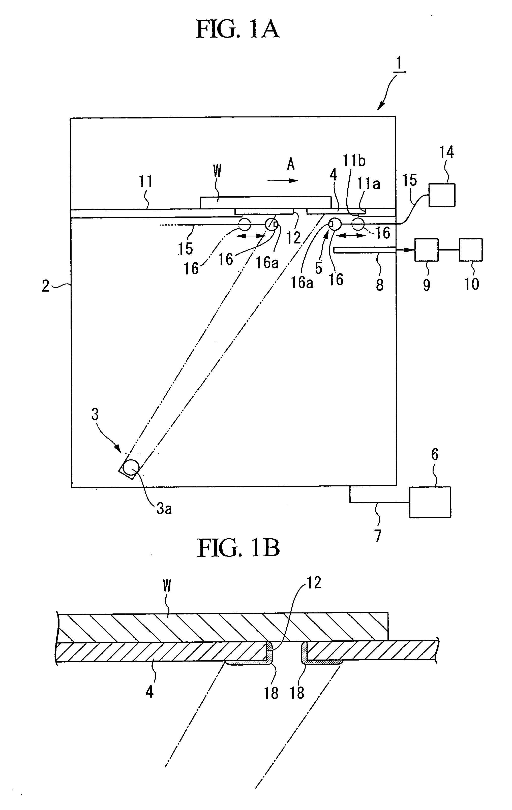
[0058]FIG. 1A is a cross-sectional view of an embodiment of the manufacturing apparatus of this invention, and FIG. 1B is a cross-sectional view of a part of the manufacturing apparatus of this invention.

[0059] In FIG. 1, reference numeral 1 represents a manufacturing apparatus for manufacturing an oriented film (hereinafter referred to as the manufacturing apparatus).

[0060] The manufacturing apparatus 1 forms an oriented film made of an inorganic material on the surface of a substrate W constituting a constituent member of the liquid crystal device.

[0061] The manufacturing apparatus 1 includes a film formation chamber 2 constituted as a vacuum chamber, an evaporating section 3 for sublimating an inorganic material of which the oriented film material is made, a shielding plate 4 arranged between the evaporating section 3 and the substrate W, and a cleaning device 5 (cleaning section) clea...


PUM


Abstract

A manufacturing apparatus for manufacturing an oriented film of a liquid crystal device holding a liquid crystal between a pair of substrates facing each other, includes: a film formation chamber; an evaporation section evaporating an oriented film material on the substrate by a physical vapor deposition, and forming the oriented film in the film formation chamber; a shielding plate formed between the evaporation section and the substrate, having an elongated opening for selectively evaporating the oriented film material, and covering an area of the substrate on which the oriented film is not formed; and a cleaning section providing a cleaning medium for removing the oriented film material adhered on the shielding plate, toward the opening of the shielding plate, and on the side of the shielding plate that faces the evaporation section.

Description

CROSS-REFERENCE TO RELATED APPLICATION [0001] This application claims priority on Japanese Patent Application No. 2005-205468, filed Jul. 14, 2005, the contents of which are incorporated herein by reference. BACKGROUND [0002] 1. Technical Field [0003] The present invention relates to a manufacturing apparatus for an oriented film, a liquid crystal device, and an electronic device. [0004] 2. Related Art [0005] A liquid crystal device has been used as a photo-modulation section in a projection display device such as a liquid crystal projector, etc. [0006] Such a liquid crystal device includes a sealant arranged at the periphery between a pair of substrates and a liquid crystal layer sealed at its center. [0007] Electrodes for applying a voltage to the liquid crystal layer are formed on the side of an inner surface of the pair of substrates, and an oriented film for controlling the orientation of liquid crystal molecules when applying a non-selective voltage is formed on the side of th...

Claims


Application Information

Patent Timeline
IPC IPC(8): G02F1/1337
CPCC23C14/044G02F2001/1316G02F1/133734C23C14/545G02F1/1316G02F1/13G02F1/1337
Inventor NAGATA, YASUSHISHIMIZU, YUICHI
Owner SEIKO EPSON CORP
Learn More