

Laser ablation apparatus useful for hard tissue removal
a laser ablation and hard tissue technology, applied in boring tools, medical science, dentistry, etc., can solve the problems of inability to focus to a spot much smaller than the fiber diameter, inability to reduce the quality of laser beams after passing through fibers, and inability to minimize the removal of healthy tissue, so as to reduce the pain level, increase the speed of hard tissue removal, and minimize the effect of healthy tissue removal
- Summary
- Abstract
- Description
- Claims
- Application Information
AI Technical Summary
Benefits of technology
Problems solved by technology
Method used
Image

Examples
Embodiment Construction
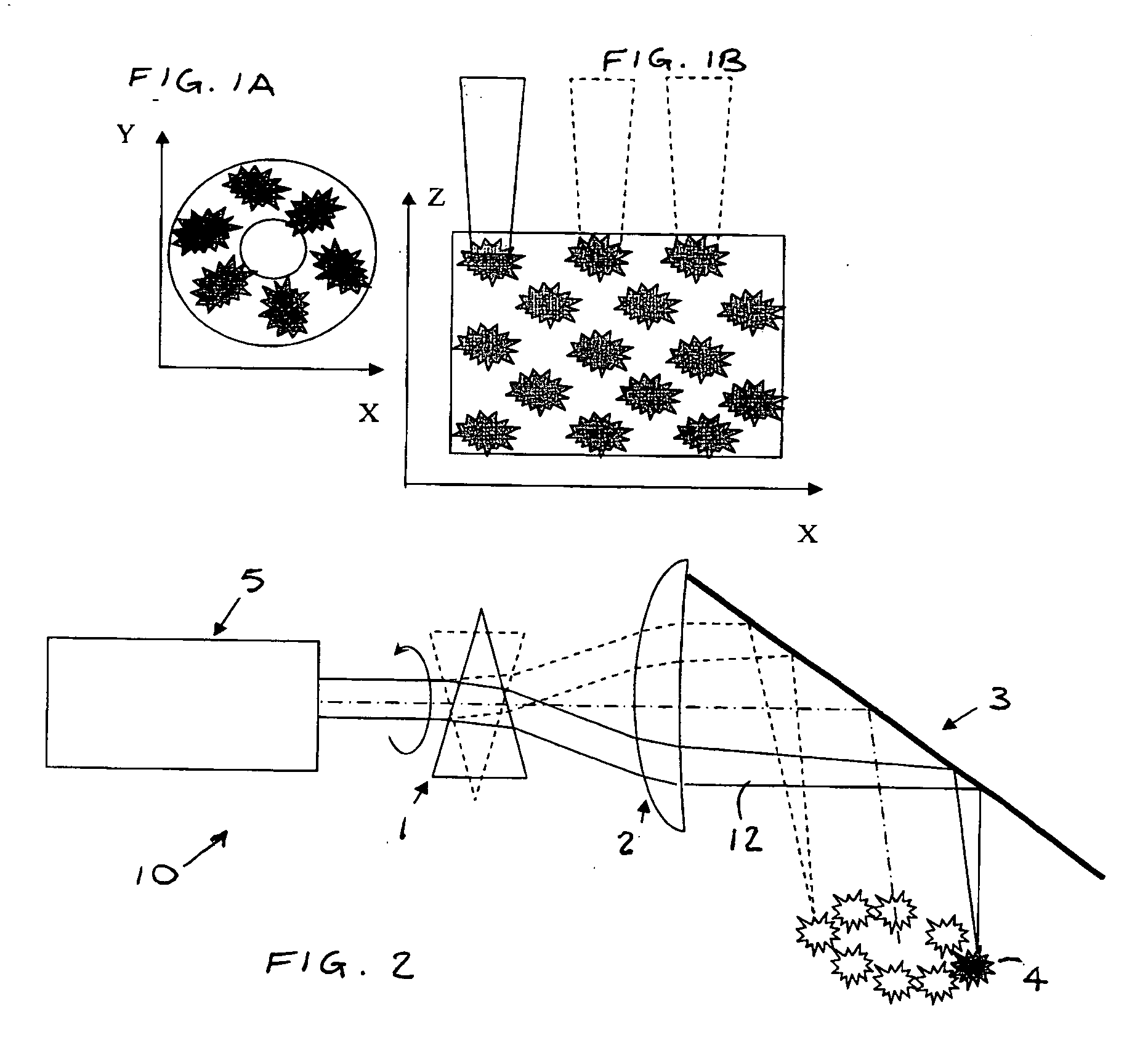
[0011] Reference is now made to FIG. 2, which illustrates laser ablation apparatus 10, constructed and operative in accordance with an embodiment of the present invention.
[0012] The laser ablation apparatus 10 may include a laser source 5 for generating laser beams 12 in a wavelength range suitable for ablating hard dental tissue. For example, the laser beams 12 may have a wavelength in a range of 2700 nm-3000 nm. In a preferred embodiment, the laser source 5 may be an erbium laser, e.g., an Er:YAG laser with an emission wavelength of 2940 nm. The laser source 5 may have a beam quality of at least M2=10 or 30, and may have an energy level in a range of 0.01-2 J at the target surface. (As is known in the art, the beam quality M2 is the ratio of the laser beam's multimode diameter-divergence product to the ideal diffraction limited (TEM00) beam diameter-divergence product.) In one embodiment, the laser source 5 may be pulsed and have a frequency level in a range of 1-200 Hz. In anoth...
PUM
 Abstract
Description
Claims
Application Information