Rare earth permanent magnet, making method, and permanent magnet rotary machine

a permanent magnet, making method technology, applied in the direction of magnetic materials, inductance/transformer/magnet manufacture, magnetic bodies, etc., can solve the problems of loss of remanence, inability to measure practically acceptable, and the likelihood of demagnetization, etc., to achieve low eddy current, high coercive force, and high remanence

Active Publication Date: 2007-01-25
SHIN ETSU CHEM IND CO LTD
View PDF3 Cites 66 Cited by
  • Summary
  • Abstract
  • Description
  • Claims
  • Application Information

AI Technical Summary

Benefits of technology

[0023] The R—Fe—B sintered magnet of the invention has minimized eddy current, a high remanence, and a high coercive force suited for permanent magnet rotary machines. A permanent magnet rotary machine using the magnet is advantageous.

Problems solved by technology

Permanent magnets are situated in rotary machines such that they are exposed to high temperature due to the heat generated by windings and cores and have a likelihood of demagnetization by the diamagnetic field from the windings.
Therefore, as long as the above approach is taken to increase coercive force, a loss of remanence is unavoidable.
However, this measure cannot be practically acceptable because it compromises densification by sintering.
An alternative method of sintering at lower temperatures while applying stresses by means of a hot press or the like enables densification, but poses the problem of extremely reduced productivity.
However, there is still left the problem of poor productivity associated with the deposition of metal coating by sputtering or the like.
This gives rise to a problem in high capacity rotary machines.
The method including bonding finely divided magnet segments and consolidating into a magnet of the desired size has the problem that more steps are involved in the magnet manufacturing process, leading to an increase of manufacturing cost and a lowering of magnet weight-basis yield.
Although one might consider to use magnet segments as such without bonding and consolidation, it is difficult to assemble and secure discrete magnet segments in a rotor against the repulsion between the magnet segments.

Method used


Image

  • Rare earth permanent magnet, making method, and permanent magnet rotary machine
  • Rare earth permanent magnet, making method, and permanent magnet rotary machine
  • Rare earth permanent magnet, making method, and permanent magnet rotary machine

Examples


example

[0070] Examples are given below for illustrating the present invention, but the scope of the invention is not limited thereby. In Examples, the filling factor of dysprosium oxide or dysprosium fluoride in the magnet surface-surrounding space is calculated from a weight gain of the magnet after powder treatment and the true density of powder material.

examples 1-1 , 2-1

Examples 1-1, 2-1 & Comparative Examples 1-1, 2-1

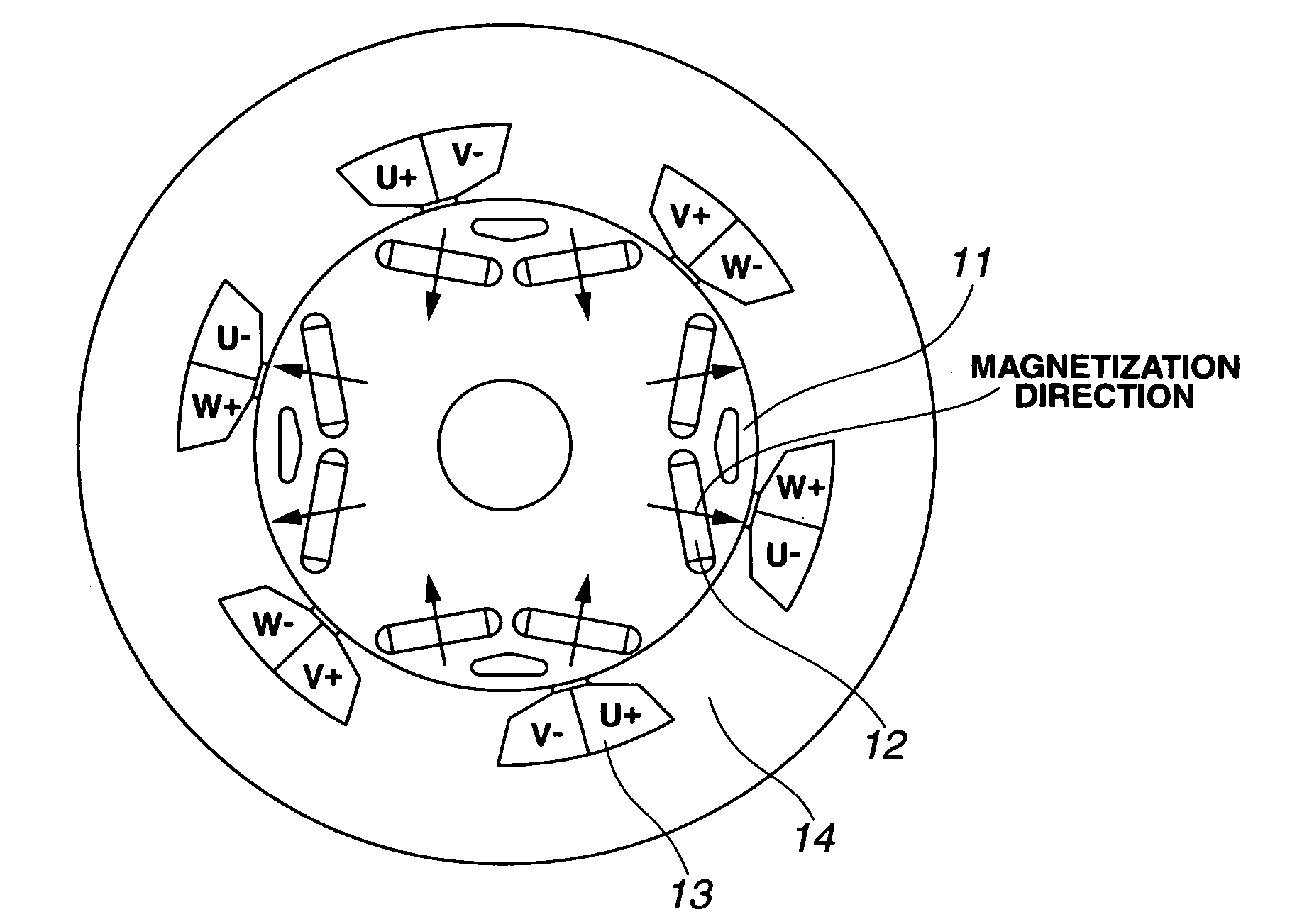
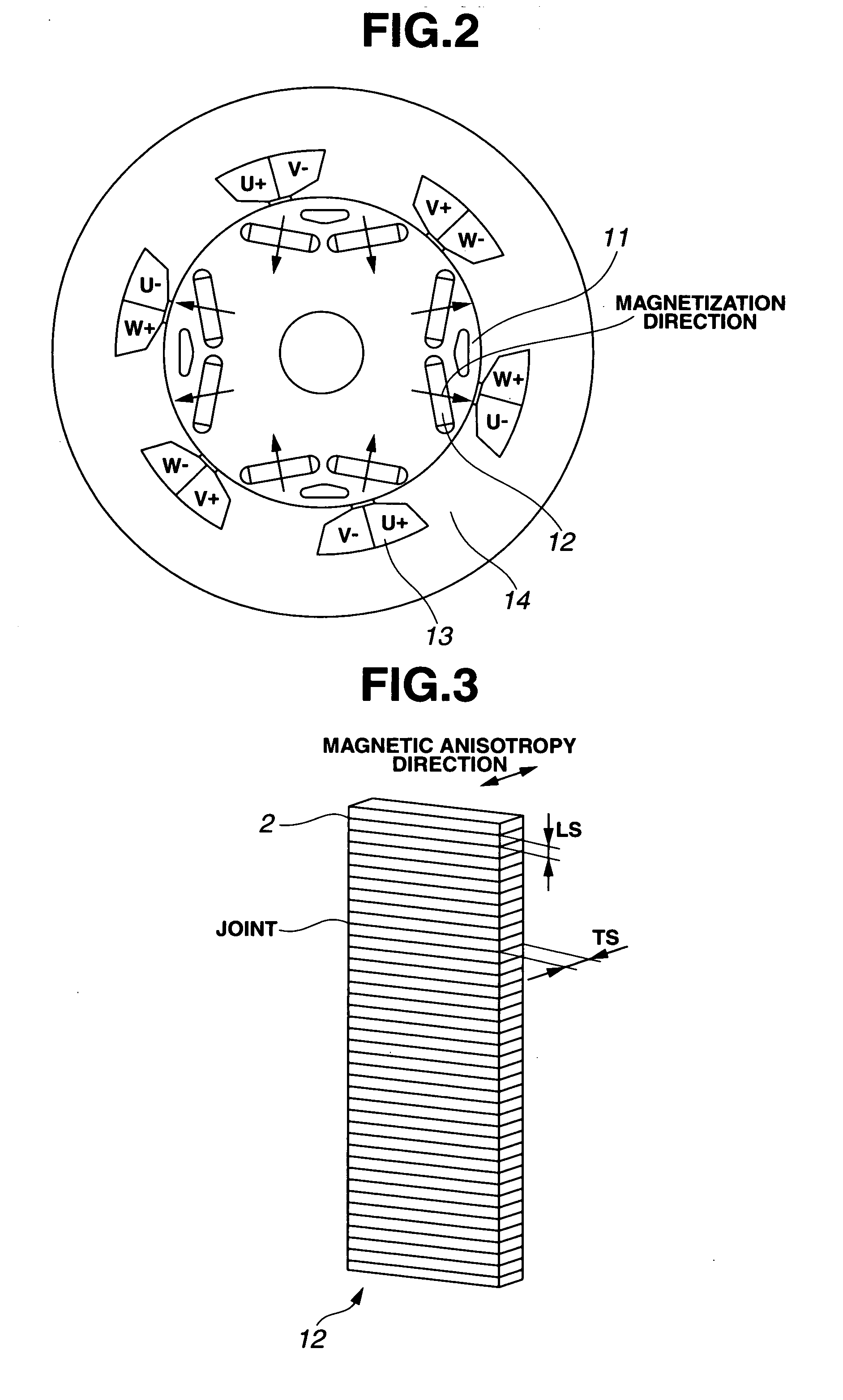
[0079] Described below is the performance of permanent magnet motors having the magnets M1 and M2 of Examples and the magnets P1 and P2 of Comparative Examples incorporated therein. FIG. 2 illustrates an exemplary interior permanent magnet motor. A rotor has a four-pole structure of 0.5 mm magnetic steel sheet laminate having permanent magnets 12 embedded therein, and a rotor yoke 11 has an outer diameter of 312 mm and a height of 180 mm. The permanent magnets 12 each have a width of 70 mm, a dimension of 20 mm in the magnetic anisotropy direction, and an axial dimension of 180 mm. Since it is difficult to manufacture a sintered magnet having a length of 180 mm, in this example, four magnet parts having a length of 45 mm were bonded together with an epoxy adhesive. A stator has a six-slot structure of 0.5 mm magnetic steel sheet laminate with a concentrated winding coil wound with 60 turns on each teeth. The coil 13 is of a three-phas...

examples 3-1 , 4-1

Examples 3-1, 4-1 & Comparative Examples 3-1, 4-1

[0085] Described below is the performance of permanent magnet motors having the magnets M3 and M4 of Examples and the magnets P3 and P4 of Comparative Examples incorporated therein. FIG. 7 illustrates an exemplary surface permanent magnet motor. A rotor has a four-pole structure and includes a rotor yoke 21 of 0.5 mm magnetic steel sheet laminate having C-shaped permanent magnets 22 disposed thereon. The rotor yoke 21 had an outer diameter of 312 mm and a height of 180 mm. The permanent magnets 22 each have a width of 160 mm, a dimension of 10 mm at the center and 3 mm at the edge in the magnetic anisotropy direction, and an axial dimension of 180 mm. Since it is difficult to manufacture a sintered magnet having a width of 160 mm or a length of 180 mm, in this example, total eight magnet segments including two in a row direction and four in a column direction were butt joined with an epoxy adhesive. A stator is the same as in Example ...


PUM

PropertyMeasurementUnit
distanceaaaaaaaaaa
distanceaaaaaaaaaa
particle sizeaaaaaaaaaa

Abstract

A rare earth permanent magnet is prepared from a sintered magnet body of a R1—Fe—B composition wherein R1 is a rare earth element inclusive of Y and Sc, by forming a plurality of slits in a surface of the magnet body, disposing a powder on the magnet body surface, the powder comprising an oxide of R2, a fluoride of R3, or an oxyfluoride of R4 wherein each of R2, R3, and R4 is a rare earth element, and heat treating the magnet body and the powder below the sintering temperature in vacuum or in an inert gas.

Description

CROSS-REFERENCE TO RELATED APPLICATION [0001] This non-provisional application claims priority under 35 U.S.C. §119(a) on Patent Application No. 2005-212265 filed in Japan on Jul. 22, 2005, the entire contents of which are hereby incorporated by reference. TECHNICAL FIELD [0002] This invention relates to a R—Fe—B system rare earth permanent magnet whose coercive force is enhanced while minimizing a decline of its remanence; a method for preparing the same; and a permanent magnet rotary machine best suited as electric vehicle motors, power generators and FA motors capable of high speed rotation. BACKGROUND ART [0003] Nd—Fe—B system permanent magnets have a growing range of application due to their excellent magnetic properties. Also in the field of rotary machines including motors and power generators, permanent magnet rotary machines utilizing Nd—Fe—B system permanent magnets were developed to meet the recent demand for size, profile and weight reductions, performance enhancement an...

Claims


Application Information

Patent Timeline
Patent Type & Authority Applications(United States)
IPC IPC(8): H01F1/03
CPCB22F3/24H01F41/0293B22F2003/245B22F2003/248B22F2998/00B22F2998/10C22C38/005H01F1/0577H02K1/278H02K15/03B22F2003/242C22C33/0278B22F3/10B22F2201/10B22F2201/20H02K1/276
Inventor MIYATA, KOJIHIROTA, KOICHINAKAMURA, HAJIMEMINOWA, TAKEHISA
Owner SHIN ETSU CHEM IND CO LTD
Why Eureka
Try Eureka