Method and apparatus for implementing fault tolerant phase locked loop (PLL)

Inactive Publication Date: 2007-01-25
GOOGLE LLC
View PDF10 Cites 3 Cited by
  • Summary
  • Abstract
  • Description
  • Claims
  • Application Information

AI Technical Summary

Benefits of technology

[0009] In accordance with features of invention, the effects of isolated hard failures and SEUs, which can cause errors, are significantly lowered. The present invention is especially applicable to radiation hardening techniques without requiring semiconductor device innovations.

Problems solved by technology

If the PLL operates at too slow a speed, the processing throughput of the system is degraded.
If the PLL operates at too high a speed, the system may not function since critical operations may not complete between clock signals.
A hard failure of one or more latches can force the PLL to fail or operate at an incorrect speed.
Likewise, latches are subject to soft errors, usually referred to as single event upsets (SEUs).
This can cause the content of the latch to change states, forcing the PLL to the wrong frequency.
Since a major source of the subatomic particles are cosmic in origin, the SEU can be a minor problem in terrestrial and low altitude avionic systems but a moderate cause of failure in high altitude and space applications.

Method used


Image

  • Method and apparatus for implementing fault tolerant phase locked loop (PLL)
  • Method and apparatus for implementing fault tolerant phase locked loop (PLL)
  • Method and apparatus for implementing fault tolerant phase locked loop (PLL)

Examples


Embodiment Construction

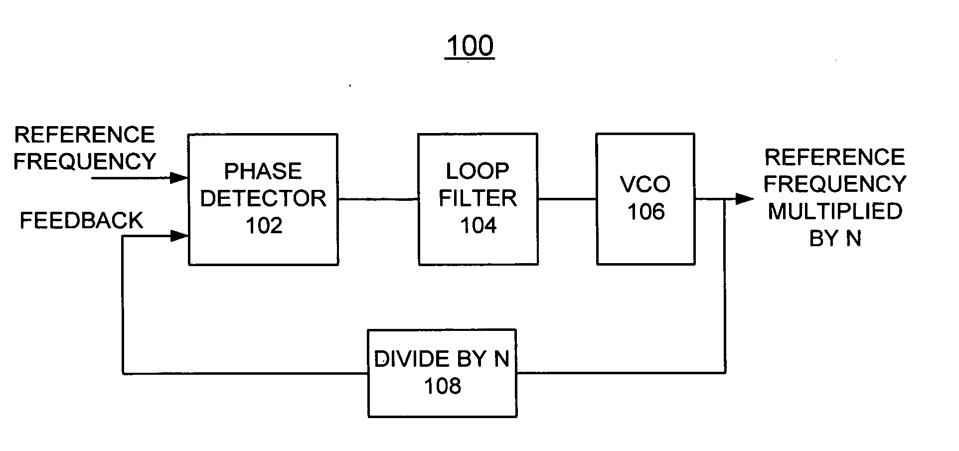
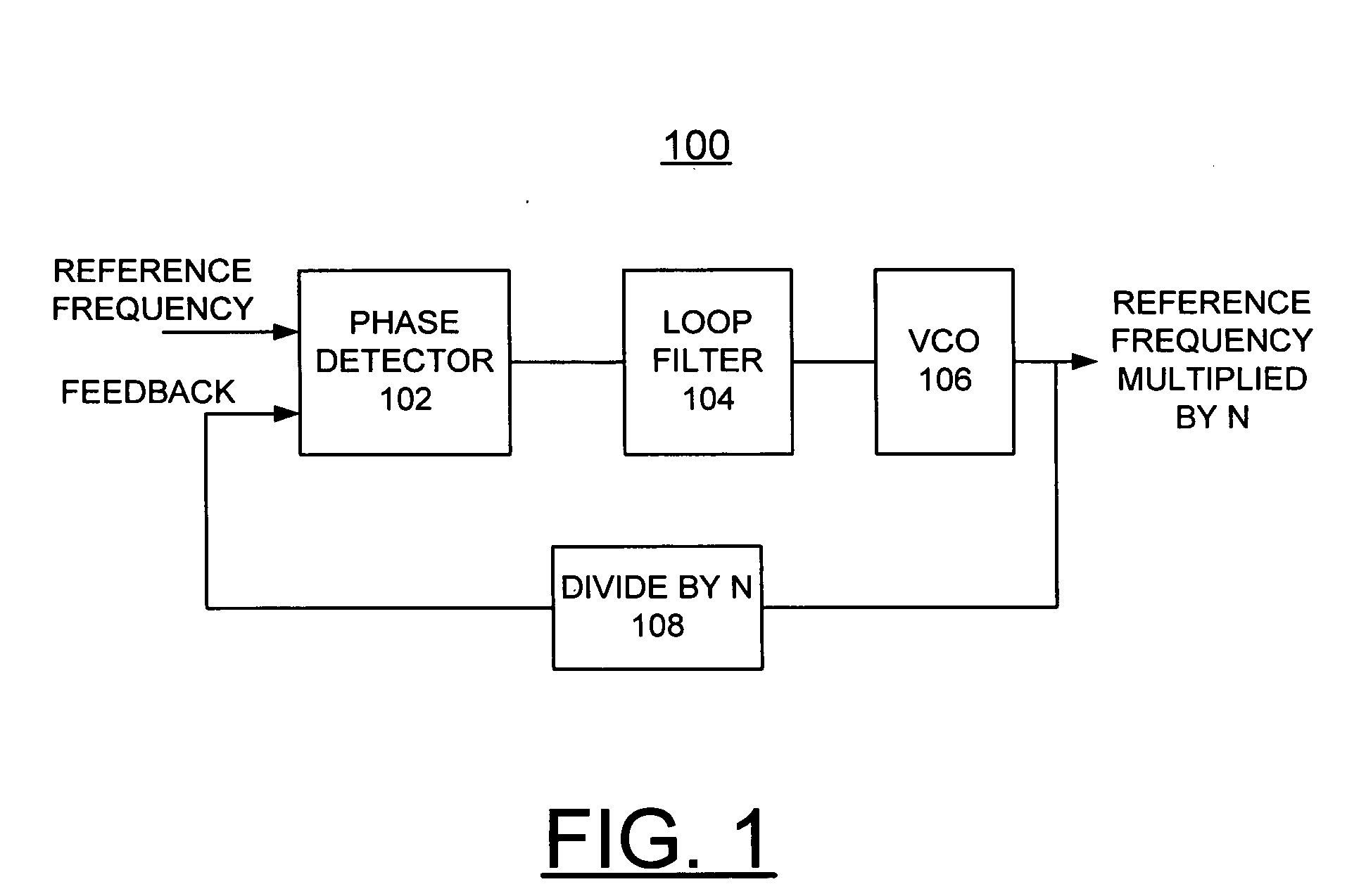
[0014] Having reference now to the drawings, in FIG. 1, there is shown a Phase Locked Loop (PLL) circuit generally designated by the reference character 100 in accordance with the preferred embodiment. PLL circuit 100 is a closed loop system, having feedback. In FIG. 1, PLL circuit 100 is shown in simplified form sufficient for understanding the present invention.

[0015] PLL circuit 100 includes a phase detector 102 that compares an input reference frequency signal REFERENCE FREQUENCY to an output feedback frequency signal FEEDBACK. Phase detector 102 generates an error signal at its output responsive to applied FEEDBACK and REFERENCE FREQUENCY signals. The generated error signal is applied to a loop filter 104, implemented by a low pass filter. When the inputs to the phase detector 102 are both of the same frequency, the output of the loop filter 104 is a stable DC value. The output of the loop filter 104 is applied to a Voltage Controlled Oscillator (VCO) 106, which varies its fre...


PUM


Abstract

A method and apparatus are provided for implementing a fault tolerant phase locked loop (PLL). The PLL circuit includes a divide by N circuit defined by a plurality of sub-divide by N functions, each providing a feedback frequency signal applied to a voter circuit. The voter circuit provides an output feedback frequency signal based upon a majority vote of the sub-divide by N functions.

Description

FIELD OF THE INVENTION [0001] The present invention relates generally to the data processing field, and more particularly, relates to a method and apparatus for implementing a fault tolerant phase locked loop (PLL). DESCRIPTION OF THE RELATED ART [0002] Phase locked loop (PLL) circuits are widely used in many different applications and are the heart of most digital systems. Typically, PLL circuits provide a system clock or timing signal which dictates the cycle time at which a digital system operates. When implementing a PLL on a CMOS microprocessor or other logic chip for on-chip clock generation, a wide range of process variation can occur. If the PLL operates at too slow a speed, the processing throughput of the system is degraded. If the PLL operates at too high a speed, the system may not function since critical operations may not complete between clock signals. [0003] Most modern day PLLs can be programmed to operate at different speeds, they contain volatile memory which is u...

Claims


Application Information

Patent Timeline
IPC IPC(8): H03L7/06
CPCH03L7/18H03L7/10
Inventor NOSOWICZ, EUGENE JAMES
Owner GOOGLE LLC
Why Eureka
Try Eureka