Amplifier arrangement and method of signal amplification

a signal amplification and amplifier technology, applied in the direction of amplifiers, amplifiers with semiconductor devices only, amplifiers with semiconductor devices, etc., can solve the problems of increasing the overall space required, part of the power loss via switching elements, etc., to reduce the high-frequency power loss, improve the average amplification efficiency, and high efficiency

Active Publication Date: 2007-01-25
APPLE INC
View PDF4 Cites 14 Cited by
  • Summary
  • Abstract
  • Description
  • Claims
  • Application Information

AI Technical Summary

Benefits of technology

[0011] The circuit illustrated reduces the high-frequency power loss and enables the use of switching means that also work with low power. Moreover, the impedance transformer circuit presented will attain a high level of efficiency in the output stage of the amplifier with adjustable amplification, and consequently the average amplification efficiency will be improved. The term amplification efficiency is understood to be the ratio of power output by the amplifier to the power expended. By increasing the load impedance by means of suitable connection or disconnection of the at least two components, the amplification of the amplifier with adjustable amplification increases, whereby on the one hand a signal input level in the amplifier can be reduced. In addition, the power consumption of the amplifier arrangement can also be reduced, which results in an improvement in operating duration for mobile communication devices in particular.
[0012] In a further embodiment of the invention, the amplifier arrangement contains a matching network connected on the input side to the output of the impedance transformer circuit and the at least two switchable elements. It is thus also possible to achieve a matching, for example to an antenna connected to the matching network. In another embodiment of the invention, the at least two elements comprise in each case an inductive component which influences the impedance at the output of the impedance transformer circuit. The use of inductive components as reactance elements enables the realization of Class A or Class AB amplifier stages with a very high amplification efficiency.

Problems solved by technology

In the embodiment shown in the publication, however, part of this power is lost via the switching elements for connecting or disconnecting the individual capacitances, particularly if the output power is high.
Moreover, the switches designed for a high output power require a relatively large chip area, resulting in an increase in the overall space required.

Method used


Image

  • Amplifier arrangement and method of signal amplification
  • Amplifier arrangement and method of signal amplification
  • Amplifier arrangement and method of signal amplification

Examples


Embodiment Construction

[0022] One or more implementations of the present invention will now be described with reference to the attached drawings, wherein like reference numerals are used to refer to like elements throughout, and wherein the illustrated structures are not necessarily drawn to scale.

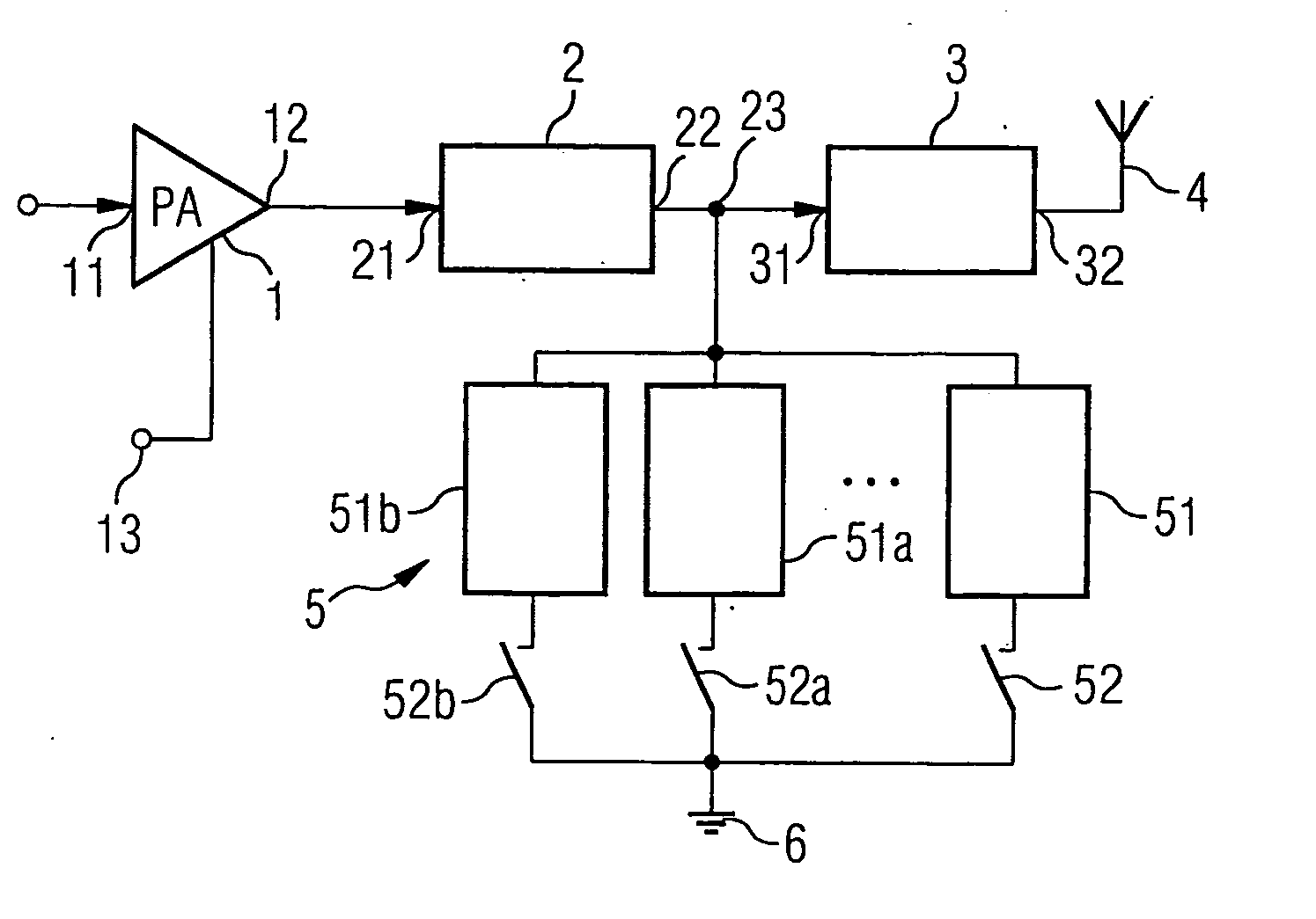
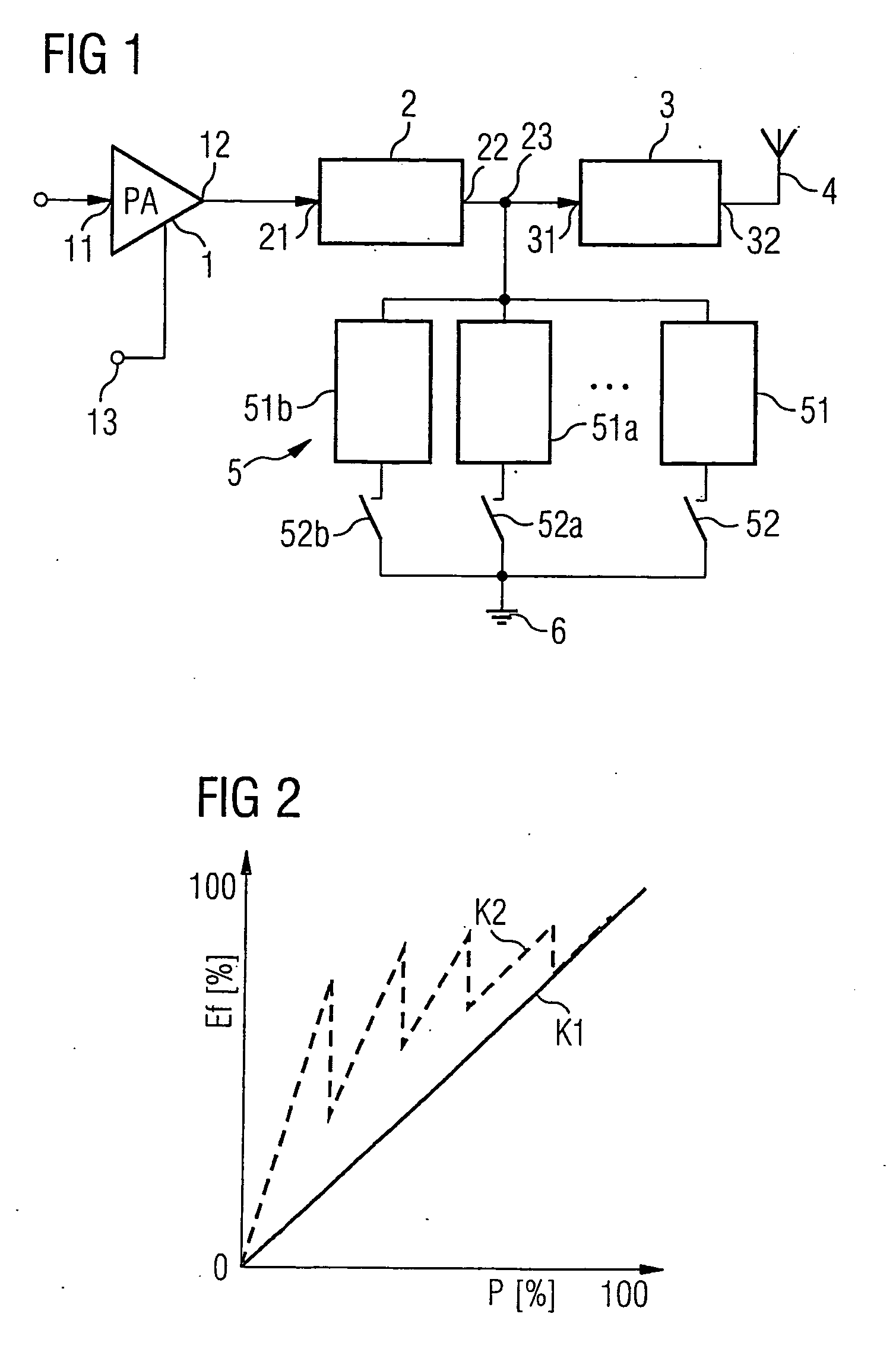
[0023]FIG. 1 shows a block circuit diagram of one embodiment of the invention. The amplifier arrangement illustrated is realized as an integrated circuit in a semiconductor body, not shown here in detail. It contains an amplifier 1 with an input 11 for supplying a signal to be amplified. Said signal is output at the output 12. In addition, the power amplifier 1 has a control terminal 13, to which an actuating signal for setting its amplification can be supplied. The power amplifier 1 sets its average amplification at the control terminal 13 by means of an actuating signal.

[0024] The output 12 of the power amplifier 1 is connected to an input 21 of an impedance transformer circuit 2. The impedance transformer c...


PUM


Abstract

An amplifier arrangement is proposed which has an amplifier with adjustable amplification having an output. An impedance transformer circuit is connected to the output. Said circuit is designed for transforming a high output impedance of the adjustable amplifier into a low impedance at its output. The amplifier arrangement contains at least two switchable elements having a reactance, which elements are connected in each case by a first terminal to the output of the impedance transformer circuit, and by a second terminal to a reference potential terminal. The switchable elements are designed for changing the impedance at the output of the impedance transformer circuit depending on a switch position of a switching means. A load impedance at the output of the amplifier is consequently varied by simple means when the output level of the amplifier changes.

Description

REFERENCE TO RELATED APPLICATIONS [0001] This application claims the benefit of the priority date of German application DE 10 2005 032 093.7, filed on Jul. 8, 2005, the contents of which are herein incorporated by reference in their entirety. FIELD OF THE INVENTION [0002] The present invention relates to an amplifier arrangement. The invention furthermore relates to a method of signal amplification. BACKGROUND OF THE INVENTION [0003] Power amplifiers that have a low power consumption while at the same time being highly efficient are required within the transmission path in mobile communication devices, in particular at the output of the transmission path. The power amplifiers should be able to amplify both signals having a substantially constant envelope and signals having a variable envelope. Signals having a constant amplitude or envelope respectively are used, inter alia, in the Bluetooth and GSM mobile communication standards. Signals in which the information to be transmitted i...

Claims


Application Information

Patent Timeline
Patent Type & Authority Applications(United States)
IPC IPC(8): H03G3/00
CPCH03F1/56H04B1/0458H03F3/19
Inventor ITKIN, GRIGORYGROMORUSHKIN, VIKTORCHUGUNOV, IGOR
Owner APPLE INC
Why Eureka
Try Eureka