
Communication protocol for networked devices

Active Publication Date: 2007-01-25
LOGITECH EURO SA
View PDF9 Cites 53 Cited by
  • Summary
  • Abstract
  • Description
  • Claims
  • Application Information

AI Technical Summary

Benefits of technology

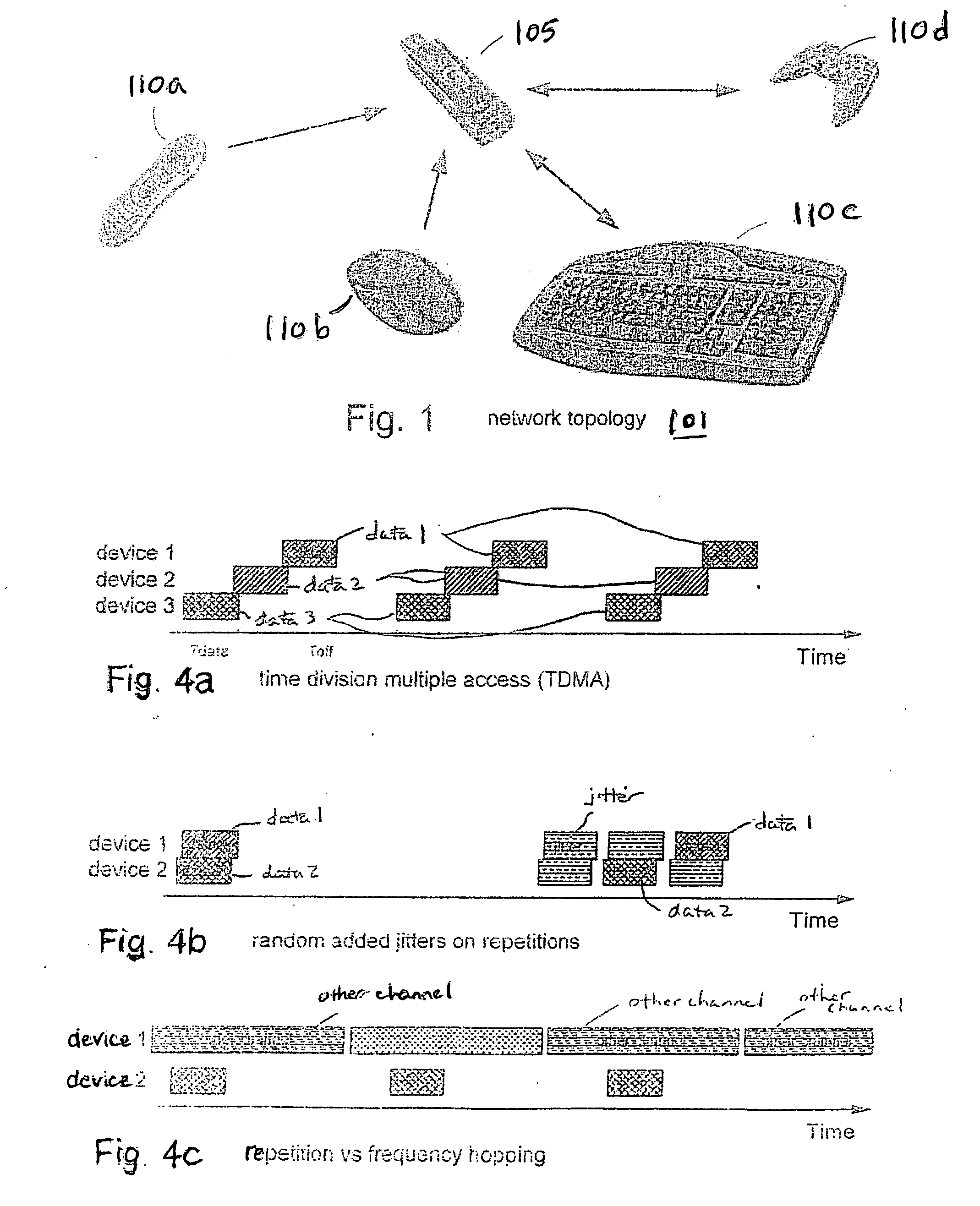
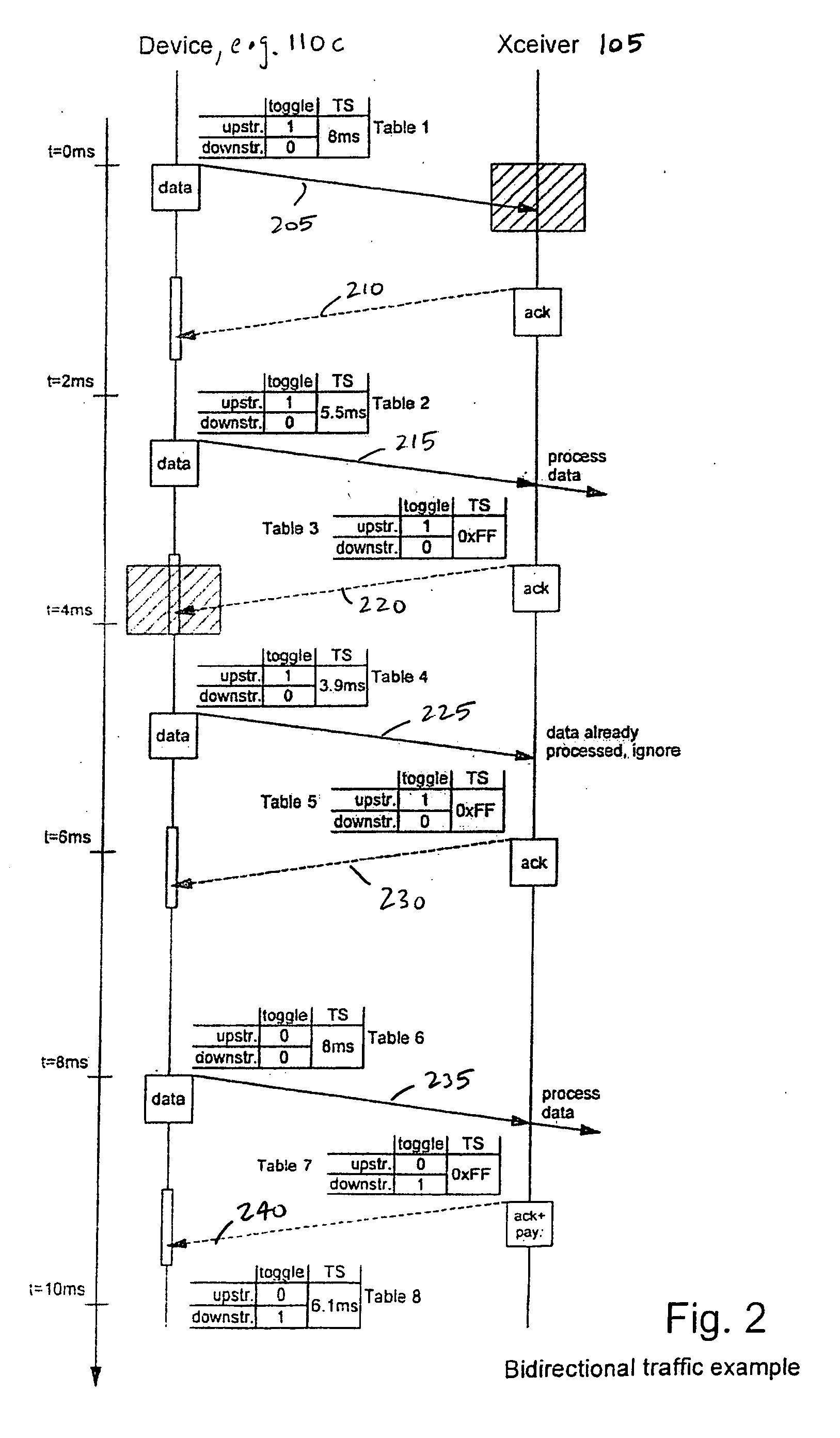
[0013] In one embodiment, at least one human interface device within the network may use a “mixed transmission mode.” A mixed transmission mode allows for switching between unidirectional to bidirectional transmission modes. Mixed transmission mode allows for reduced power consumption and optimized data transmission. In addition, for a device capable of bidirectional linking, information may be split and transmitted in two categories. A first category would require reliability, albeit with some cost of time and energy, as the device waits for an acknowledgement from the receiver. A second category would allow for information to occasionally drop because it allows for renouncement of acknowledge. The present communication protocol can also be structured to allow devices to mix reports that require an acknowledge and reports that do not require acknowledge. Thus, the communication protocol has flexibility to function with devices configured to generate bidirectional traffic or unidirectional traffic depending on the importance of the data for transportation, e.g., greater reliability of data transportation.
[0014] In one embodiment (and independently from to the mixed configuration) device is its own master and can send out data when necessary. This beneficially reduces power consumption and complexity on the human interface device side by eliminating the need to consistently listen to a beacon signal when no data is transmitted and suppressing initial latency when data is transmitted.
[0015] According to a second aspect of the present invention, the communication protocol includes features for optimizing the transmission link between the transceiver and any of the human interface devices of the network. These optimized transmission features consist in avoiding as much as possible collisions with other applications. In an example embodiment, smart timing is implemented to send data in order to avoid collisions with applications using frequency hopping transmission, e.g., Bluetooth.
[0017] A third aspect of the present invention includes a smart pairing by which the transceiver and each human interface device of the network exchange information such as the minimum time between transmissions of two consecutive data packets. This smart pairing involves data initially transmitted between the transceiver and each device in order to optimize future transmissions between them. Thus, during this “free time” (minimum time between two transmissions) the transceiver can rest to save power or may open a negotiation procedure with any of the devices to adjust this period of time between two transmissions or open a new negotiation in order to free bandwidth for the transceiver, or spend time on other tasks. As the transceiver knows when to expect next report it may detect a link-loss condition in case no data is received, and possibly even take actions to recover the link without the user noticing. Thus, advantages of smart pairing include power consumption reduction and communication optimization.
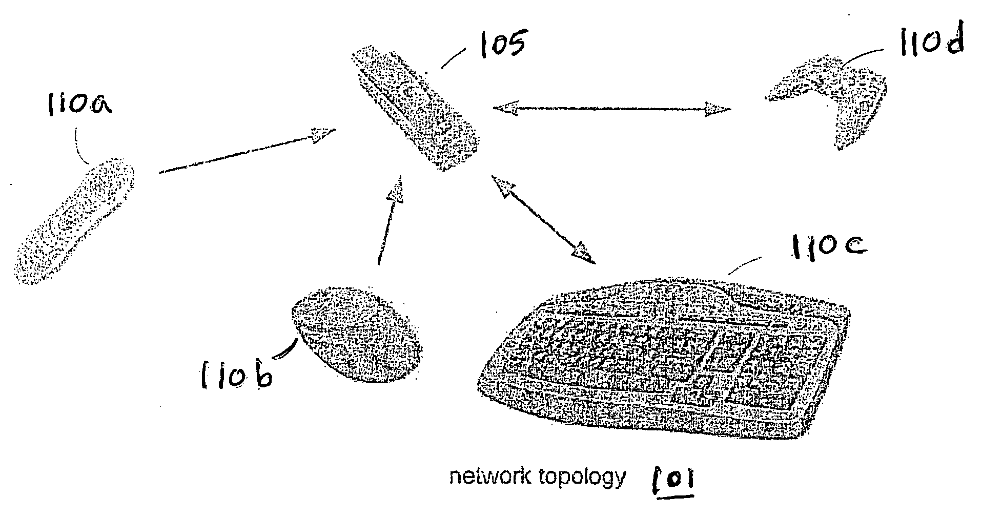
[0019] With respect to the keyboard, it might feature a screen, e.g., a liquid crystal display screen. The host may be configured to send data to the keyboard for display on the screen. The keyboard can be configured to receive data from the host display on the screen while the user continues typing. Such a configuration leverages a bidirectional link. Thus, in this overall desktop configuration, the mouse can be configured with a unidirectional link with respect to the host, which significantly reduces the complexity of the mouse, and a the keyboard can be configured with a bidirectional link with the host allowing for greater keyboard related functionality. The configuration, therefore, requires a nominal amount of hardware and software resources relative to solutions such as Bluetooth.

Problems solved by technology

However, although systems using such protocols are less complex, they also have significant limitations that include lower bit rates and shorter communication ranges.
However, systems using such protocols are more complex to design and implement.
This results in greater development and implementation costs as well as increased use of resources such as transmission and processing power, which increases power consumption.
However, unidirectional transmission requires transmitting additional, redundant information in order to compensate the lack of reliability of the link.
However, such configurations cost time and energy because devices must wait for acknowledgement from the receiver.
In addition, such conventional networks do not offer the necessary flexibility for various kinds of applications.
In addition to the problems outlined above, other problems also exist with conventional HID configurations (or applications).
However, some ISM bands do not have worldwide acceptance and approval.
The use of such high frequency bands is not without costs.
It increases system complexity, and in turn, costs.
In addition, such systems increase power consumption.
This reduces the operational time of battery powered type devices.
Moreover, devices operating in this same frequency band have problems of collision with each other.
This causes a reduction or overall failure of data throughput.
However, Bluetooth is a very complex protocol.
Although Bluetooth devices in some configurations give an appearance of being unidirectional devices, the communications are in fact bidirectional, not unidirectional.
Specifically, careful study of the low-level communications structure shows that the underlying radio communication is bidirectional, even though transmission in one of those directions does not transport useful user data.
Thus, the extraneous data send in such devices unnecessarily occupy bandwidth and increases power consumption.
This, the configuration places cost, complexity and reliability at the places considered to be most relevant within the network.

Method used


Image

  • Communication protocol for networked devices
  • Communication protocol for networked devices
  • Communication protocol for networked devices

Examples


Embodiment Construction

[0029] The Figures (FIGS.) and the following description relate to preferred embodiments of the present invention by way of illustration only. It should be noted that from the following discussion, alternative embodiments of the structures and methods disclosed herein will be readily recognized as viable alternatives that may be employed without departing from the principles of the claimed invention.

[0030] Reference will now be made in detail to several embodiments of the present invention(s), examples of which are illustrated in the accompanying figures. It is noted that wherever practicable similar or like reference numbers may be used in the figures and may indicate similar or like functionality. The figures depict embodiments of the present invention for purposes of illustration only. One skilled in the art will readily recognize from the following description that alternative embodiments of the structures and methods illustrated herein may be employed without departing from th...


PUM


Abstract

A communication protocol in a wireless network of a transceiver and a plurality of devices, in which at least one device is a bidirectional device, and in which one or more other devices can be unidirectional devices. The unidirectional device communicates with the transceiver in a unidirectional mode from the device to the transceiver and the bidirectional device communicates with the transceiver either in a bidirectional mode or in an unidirectional mode from the device to the transceiver. The communication protocol is configured to determine which transmission mode is to be used for each device. Various techniques are provided in order to optimize the time and energy spent to transmit information from one peer to the other.

Description

CROSS REFERENCE TO RELATED APPLICATIONS [0001] This application claims a benefit of U.S. Provisional Application No. 60 / 693,703, filed Jun. 24, 2006, which is incorporated by reference in its entirety.BACKGROUND [0002] 1. Field of Art [0003] The present invention relates to radio frequency communication protocol and, more particularly, a flexible system comprising a network of a transceiver and several human interface devices (HIDs) using either unidirectional or bidirectional mode to communicate with the transceiver, as well as optimization of a transmission between the transceiver and the HIDs, and pairing the transceiver with the HIDs. [0004] 2. Description of the Related Art [0005] A network of wireless devices is often configured with a host transceiver communicating with one or more devices. The devices communicate through a conventional wireless communication protocol. Among existing communication protocols, low frequency protocols have the advantage of being simple and low c...

Claims


Application Information

Patent Timeline
IPC IPC(8): H04L7/00
CPCH04B7/265H04W52/0254H04W84/18H04W28/24Y02D30/70
Inventor AMBUEHL, ROLFZANONE, JEAN-DANIELARRIGO, SIMONEBIZE, XAVIER
Owner LOGITECH EURO SA
Learn More