Apparatus and method for transferring signals between a fiber network and a wireless network antenna

a technology of fiber network and wireless network, applied in electrical apparatus, radio transmission, electromagnetic transmission, etc., can solve the problems of reducing the throughput of such distant nodes, and increasing the cost of coaxial cable and fiber optic cable implementation

Inactive Publication Date: 2007-01-25
LOGUS BROADBAND WIRELESS SOLUTIONS
View PDF34 Cites 86 Cited by
  • Summary
  • Abstract
  • Description
  • Claims
  • Application Information

AI Technical Summary

Benefits of technology

[0031] According to another aspect of the preferred embodiment of the invention, the apparatus may preferably further include an enclosure. Preferably, the fiber module, the RF / packet converter, the WIMAX media access control layer, the baseband physical layer, and the radio module may be together contained within the enclosure. The enclosure may preferably be a rugged enclosure that is adapted for outdoor use so as to substantially protect components therein from outside environmental conditions. The rugged enclosure may also or alternately preferably have a rigid watertight shell so as to substantially protect components therein from outside underground conditions.

Problems solved by technology

In Wi-Fi contention access systems, all subscriber stations wishing to pass data through a wireless access point must compete for the wireless access point's attention on a substantially random basis, which can cause nodes distant from the wireless access point to be repeatedly interrupted by less sensitive closer nodes, thus greatly reducing the throughput of such distant nodes.
Moreover, extending services using coaxial cables and fiber optic cables can require significant infrastructure builds and upgrades.
Similarly, costs for such coaxial cable and fiber optic cable implementation are on the rise.
Thus far, in the prior art, there are no known systems specifically adapted to enable the use of WiMAX networks for “last mile” connectivity (i.e., from a neighborhood distribution node to an end subscriber).

Method used


Image

  • Apparatus and method for transferring signals between a fiber network and a wireless network antenna
  • Apparatus and method for transferring signals between a fiber network and a wireless network antenna
  • Apparatus and method for transferring signals between a fiber network and a wireless network antenna

Examples


Embodiment Construction

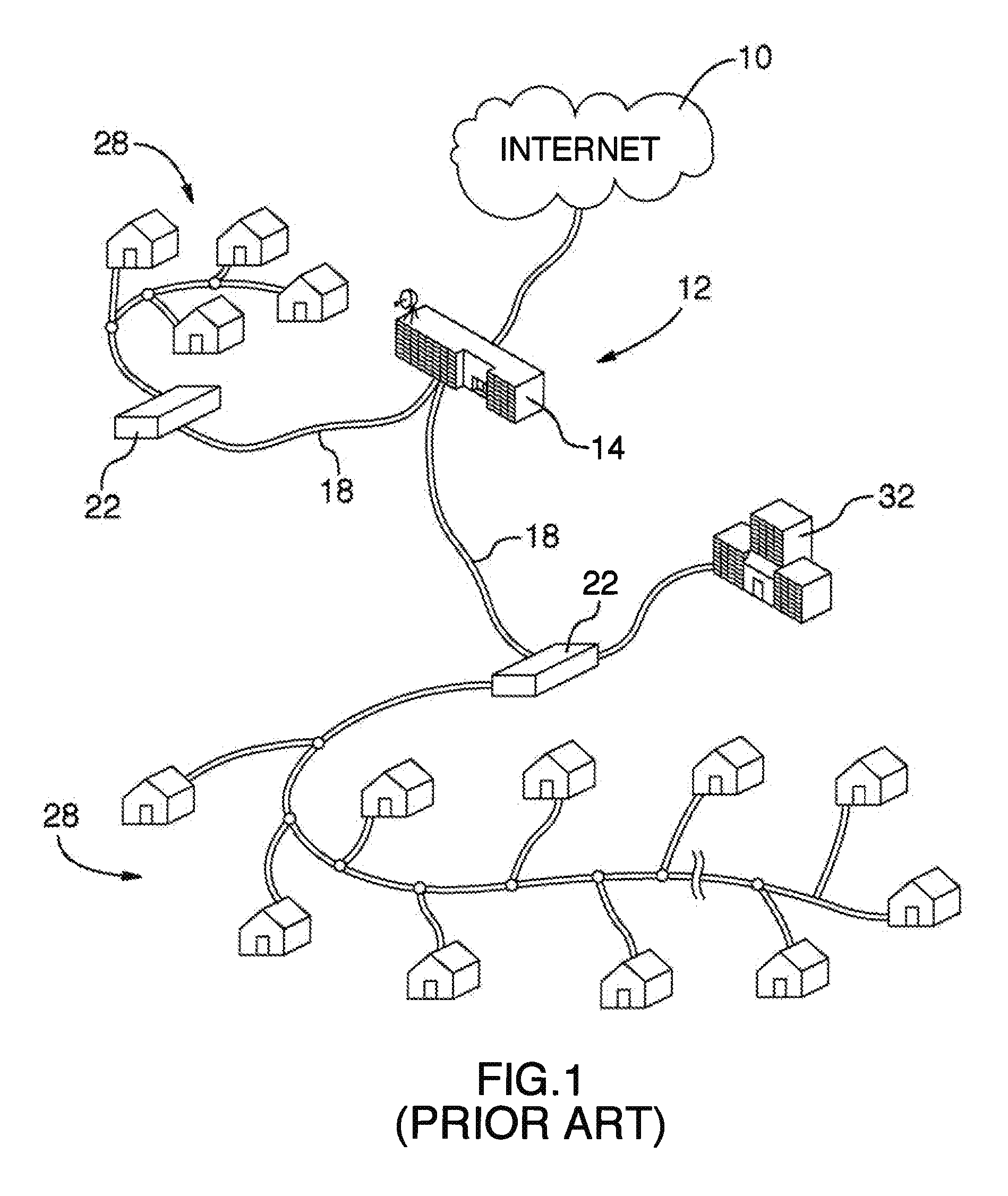
[0067]FIG. 1 depicts a prior art fiber network 12 connected to the Internet 10. The prior art network 12 may be a hybrid fiber coaxial (HFC) networks The fiber network 12 shown in FIG. 1 includes a head end cable operator 14 connected by coaxial or fiber optics cables 18 to a plurality of neighborhood distribution nodes 22. Each of the distribution nodes 22 is physically connected via a trunk and branch system of coaxial or fiber optics cables 18 to a large number of home and business subscribers 28, 32 in order to provide such subscribers with network services. That is, the fiber network 2 may generally include a “head end” where signals are received from satellite and other local sources, including the Internet and other services. At the head end, these signals are generally processed, modulated and combined to be transmitted via optical fibers at optical frequencies. The optical signals may be received at nodes and then converted back to RF signals. The fiber topology is generall...


PUM


Abstract

An apparatus and method transfers signals between a fiber network and a wireless network antenna. In a fiber to wireless stage, fiber signals are optically transferred from the fiber network and converted into RF signals compatible with the DOCSIS interface standard. The RF signals are electronically converted into data packets, the data packets are electronically converted into baseband digital signals, and the digital signals are converted into analog signals, before being transferred to the network antenna for wireless transmission. The data packets, digital signals, and analog signals are compatible with the IEEE 802.l6 wireless networking standard. Conversely, in a wireless to fiber stage, the analog signals are transferred from the antenna, and converted into digital signals, which are then electronically converted into data packets. The data packets are electronically converted into RF signals, which are next converted into fiber signals, before being optically transferred to the fiber network.

Description

FIELD OF THE INVENTION [0001] The present invention relates to the field of signal transfer between fiber and wireless networks, and more particularly, to an apparatus and method for transferring signals between a hybrid fiber coaxial system and a WiMAX wireless network antenna. BACKGROUND OF THE INVENTION [0002] WiMAX is an acronym that stands for Worldwide Interoperability for Microwave Access, and it relates to products that provide point-to-multipoint broadband wireless access and conform with the IEEE 802.16 protocol. Whereas the wireless coverage associated with earlier protocols (e.g., Wi-Fi or IEEE 802.11) has been measured in square meters, WiMAX wireless coverage has the potential to be measured in square kilometers, and proponents of the IEEE 802.16 standard contemplate wireless coverage of entire metropolitan areas (i.e., Wireless Metropolitan Area Networks or WMANs). The WiMAX specification provides for significantly increased bandwidth and stronger encryption in compar...

Claims


Application Information

Patent Timeline
Patent Type & Authority Applications(United States)
IPC IPC(8): H04B10/00
CPCH04B10/25752
Inventor RETNASOTHIE, FRANCIS E.MUTHULINGAM, SUGUNALANRETNASOTHIE, DASHAINI VICTORIA
Owner LOGUS BROADBAND WIRELESS SOLUTIONS
Why Eureka
Try Eureka