Super abrasive grain wire saw winding structure, super abrasive grain wire saw cutting device, and super abrasive grain wire saw winding method

a super abrasive wire saw and cutting device technology, applied in the direction of metal sawing devices, saw chains, manufacturing tools, etc., can solve problems such as unreeled smoothly, and achieve the effects of preventing the engagement of superabrasive wire saws, reducing the damage to the bonding material and the falling of superabrasive grains, and preventing the friction between superabrasive wire saws

Inactive Publication Date: 2007-02-01
ALLIED MATERIAL
View PDF26 Cites 54 Cited by
  • Summary
  • Abstract
  • Description
  • Claims
  • Application Information

AI Technical Summary

Benefits of technology

[0018] According to the method of winding a superabrasive wire saw configured as such, since pitch P with which the superabrasive wire saw is wound is larger than average diameter D of the superabrasive wire saw, when the superabrasive wire saw is wound around the surface of the reel portion, an intense friction between a superabrasive wire saw which is being wound and a superabrasive wire saw which has already been wound in an adjacent position is prevented. In addition, since pitch P is smaller than 2D, when the superabrasive wire saw is wound around the surface of the reel portion, the superabrasive wire saw which is being wound does not enter a gap between the adjacent superabrasive wire saws which have already been wound in a lower layer. In doing so, when the superabrasive wire saw is unreeled again from the reel portion, an intense friction between the superabrasive wire saws can be prevented. For the reasons above, according to the present invention in which pitch P is set within an appropriate range for winding the superabrasive wire saw, damage to the bonding material and falling of the superabrasive grains can be reduced.
[0019] Preferably, the step of winding the superabrasive wire saw includes the step of winding the superabrasive wire saw with winding tension corresponding to 5% to 50%, both inclusive, of a breaking strength of the superabrasive wire saw. According to the method of winding a superabrasive wire saw configured as such, since the winding tension is at least 5% of the breaking strength of the superabrasive wire saw, the superabrasive wire saw once wound around the reel portion does not loosen with time. Furthermore, since the winding tension is at most 50% of the breaking strength of the superabrasive wire saw, damage to the bonding material due to engagement of the superabrasive wire saws is prevented.
[0020] As described above, according to the present invention, there can be provided a superabrasive wire saw-wound structure, a cutting device with a superabrasive wire saw, and a method of winding a superabrasive wire saw which can reduce damage to a bonding material and falling of superabrasive grains.

Problems solved by technology

In addition, Japanese Patent Laying-Open No. 4-351222 discloses a bonding wire winding which is wound reciprocatingly to be multi-layered such that it is unreeled smoothly during a bonding operation.

Method used


Image

  • Super abrasive grain wire saw winding structure, super abrasive grain wire saw cutting device, and super abrasive grain wire saw winding method
  • Super abrasive grain wire saw winding structure, super abrasive grain wire saw cutting device, and super abrasive grain wire saw winding method
  • Super abrasive grain wire saw winding structure, super abrasive grain wire saw cutting device, and super abrasive grain wire saw winding method

Examples


example 1

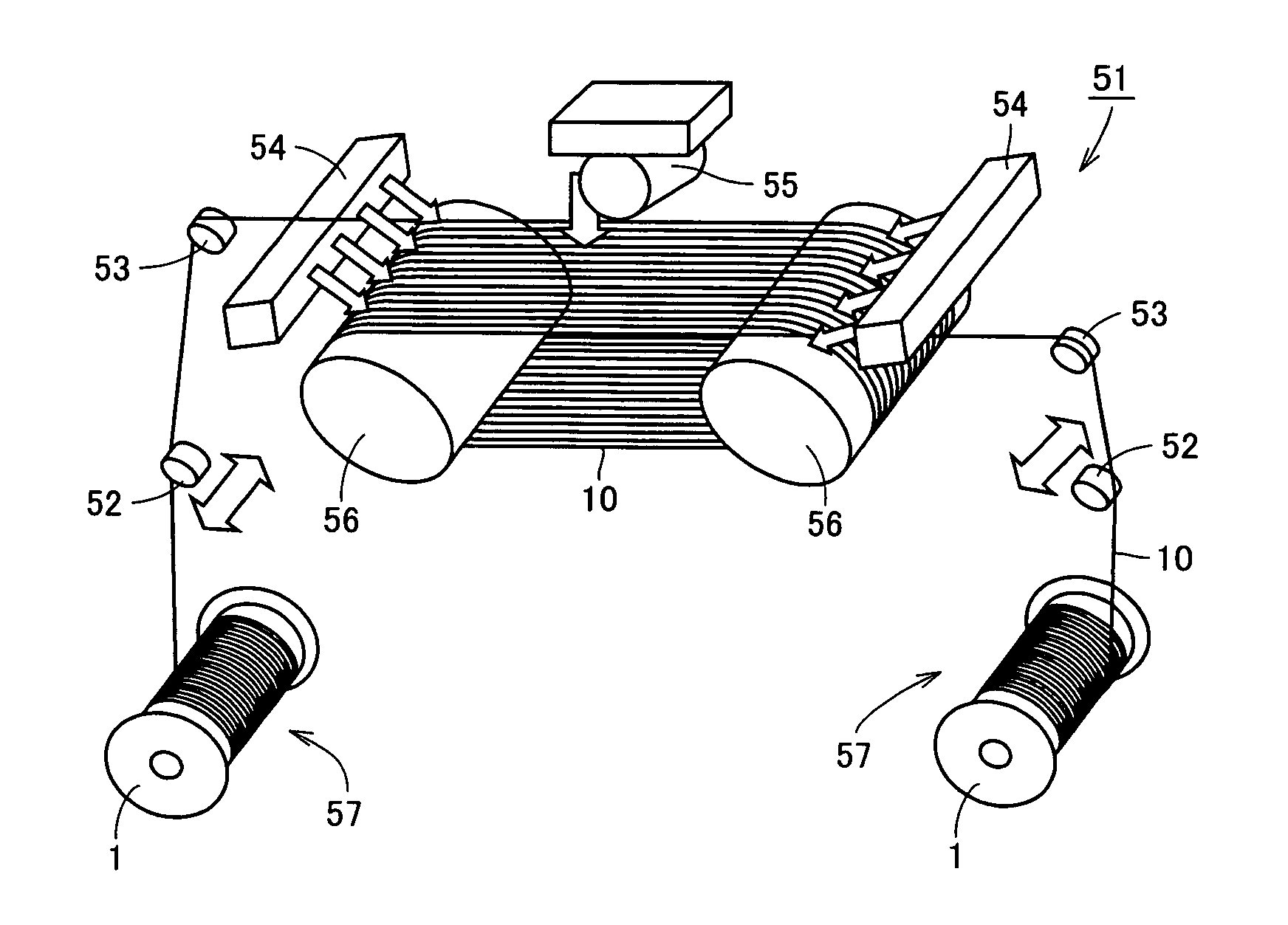
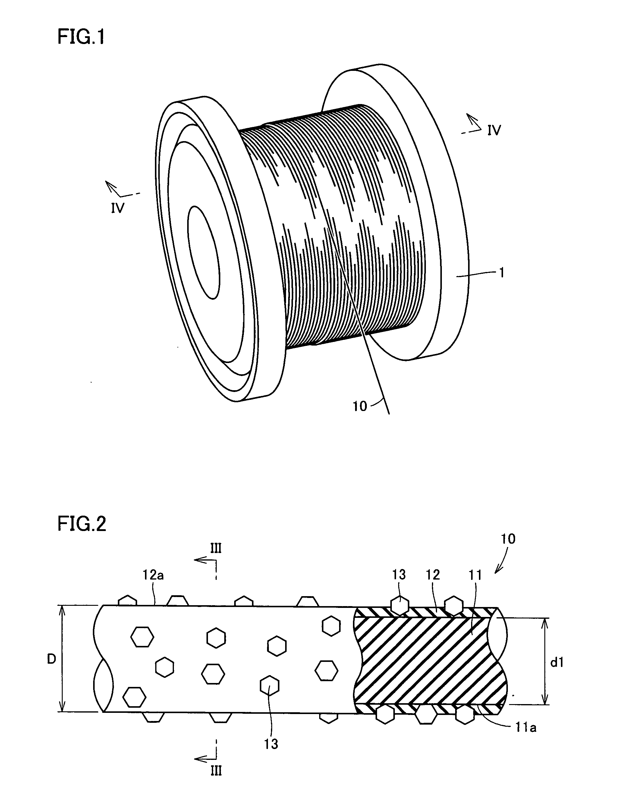
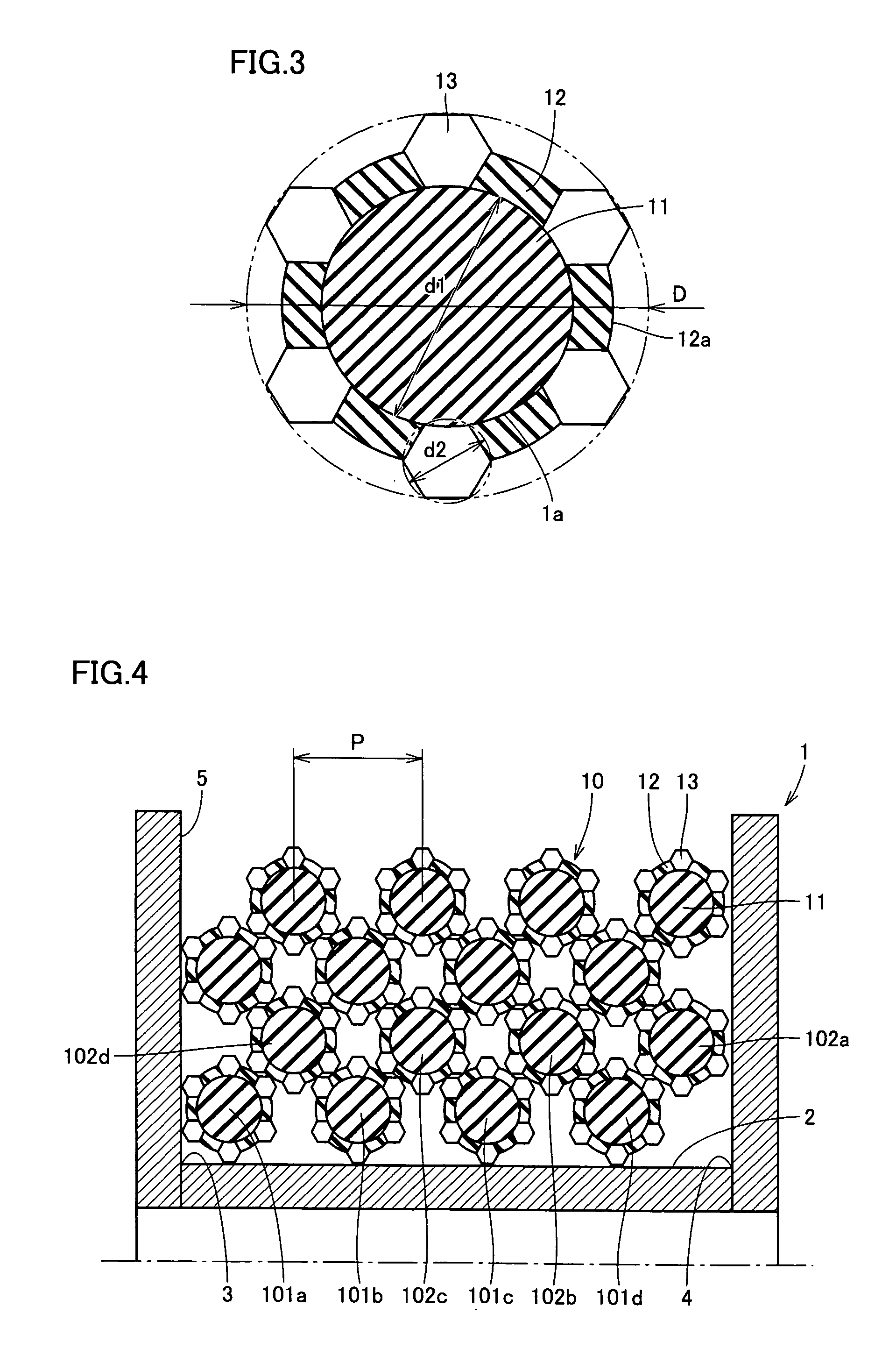
[0065] By using cutting device 51 in FIG. 7, a test was conducted to examine influences of winding pitch P of superabrasive wire saw 10 on damage to bonding material 12 and falling of superabrasive grains 13. A piano wire having average diameter d1 of 0.18 mm was used as core wire 11 of superabrasive wire saw 10. Diamond superabrasive grains having average diameter d2 of 42 μm were used as superabrasive grains 13. A phenol resin was used as bonding material 12. Average diameter D of superabrasive wire saw 10 was 0.25 mm.

[0066] Under the test conditions below, there was conducted an unreeling test in which superabrasive wire saw 10 was repeated1y reciprocated between two reels 1.

[0067] Test Conditions:

[0068] Rate of superabrasive wire saw; 800 m / min

[0069] Winding tension T; 9.8N

[0070] Winding pitch P; 0.4 mm (D

[0071] Cutting fluid; water-soluble cutting fluid

[0072] Unreeling cycle (one reciprocation is defined as one cycle); 212 cycles

[0073] After the test, superabrasiv...

example 2

[0076] Next, by using superabrasive wire saw 10 specified similarly to that of example 1, an unreeling test was conducted under the test conditions below to examine the effects of the change in winding tension T of superabrasive wire saw 10. Note that a tensile test was performed on superabrasive wire saw 10 in advance, showing that the breaking strength thereof was 78N.

[0077] Test Conditions:

[0078] Rate of superabrasive wire saw; 800 m / min

[0079] Winding tension T; 9.8N (corresponding to 12.6% of the breaking strength of superabrasive wire saw 10)

[0080] Winding pitch P; 0.4 mm (D

[0081] Cutting fluid; water-soluble cutting fluid

[0082] Unreeling cycle; 424 cycles

[0083] After the test, the observation of superabrasive wire saw 10 as in example 1 showed that a cumulative peel length of bonding material 12 was 350 mm.

example 3

[0084] By using superabrasive wire saw 10 specified similarly to that of example 1, an unreeling test was conducted according to the test conditions of example 2 with the exception that only winding tension T thereamong was set to 25.7N (corresponding to 33% of the breaking strength of superabrasive wire saw 10). After the test, the observation of superabrasive wire saw 10 as in example 1 showed that a cumulative peel length of bonding material 12 was 2300 mm.


PUM

PropertyMeasurementUnit
angleaaaaaaaaaa
diameter d1aaaaaaaaaa
diameteraaaaaaaaaa

Abstract

A superabrasive wire saw-wound structure includes a superabrasive wire saw (10) formed with an average diameter D and a reel (1). The superabrasive wire saw (10) includes a core wire (11), a bonding material (12) surrounding a surface of the core wire (11), and a plurality of superabrasive grains (13) bonded to the surface of the core wire (11) with the bonding material (12). The reel (1) includes a peripheral surface (2) having one end (3) and the other end (4). The superabrasive wire saw (10) which is to be unreeled successively toward a workpiece is wound around the peripheral surface (2) reciprocatingly between the one end (3) and the other end (4) to be multi-layered. A pitch P for winding the superabrasive wire saw (10) around the peripheral surface (2) between the one end (3) and the other end (4) satisfies a relation of D<P<2D. According to the present invention, there can be provided a superabrasive wire saw-wound structure, a cutting device with a superabrasive wire saw, and a method of winding a superabrasive wire saw which can reduce damage to a bonding material and falling of a superabrasive grain.

Description

TECHNICAL FIELD [0001] The present invention generally relates to a superabrasive wire saw-wound structure, a cutting device with a superabrasive wire saw, and a method of winding a superabrasive wire saw, and more particularly, to a bonded-abrasive type superabrasive wire saw-wound structure, a cutting device with a superabrasive wire saw, and a method of winding a superabrasive wire saw which are used for slicing a silicon ingot into silicon wafers, and performing a cutting process on various materials such as metal, resin, ore, glass, sapphire, rock crystal, SiC, and compound semiconductor. BACKGROUND ART [0002] Conventionally, a bonded-abrasive type diamond wire saw, which has diamond abrasive grains bonded to the surface of a core wire, has been proposed as an example of a superabrasive wire saw. With the diamond wire saw, a material such as a metal can be cut extremely cleanly. In addition, there is no need for a slurry having an abrasive fluid and abrasive grains blended; ins...

Claims


Application Information

Patent Timeline
Patent Type & Authority Applications(United States)
IPC IPC(8): B28D1/08B23D57/00B23D61/18B24B27/06B65H54/28
CPCB23D57/0061B65H54/2872B24B27/0633B23D61/185Y10T83/9292B24B27/06B65H54/28
Inventor NAKAI, MASANORIYAMANAKA, MASAAKIISHITOBI, YOSHIZUMI
Owner ALLIED MATERIAL
Why Eureka
Try Eureka