Electromagnetically operated friction disk clutch and rotor for a clutch of this type
- Summary
- Abstract
- Description
- Claims
- Application Information
AI Technical Summary
Benefits of technology
Problems solved by technology
Method used
Image

Examples
Embodiment Construction
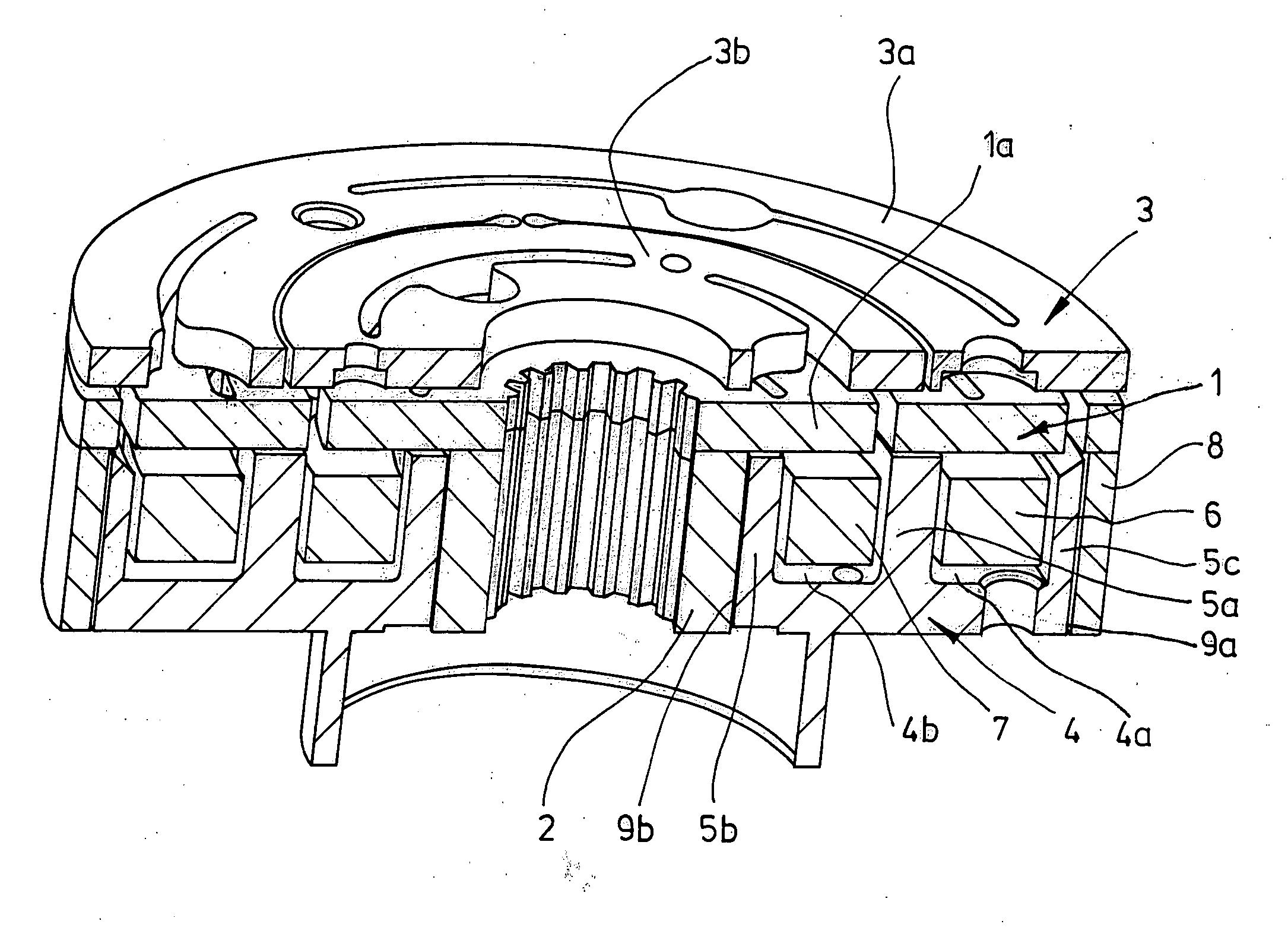
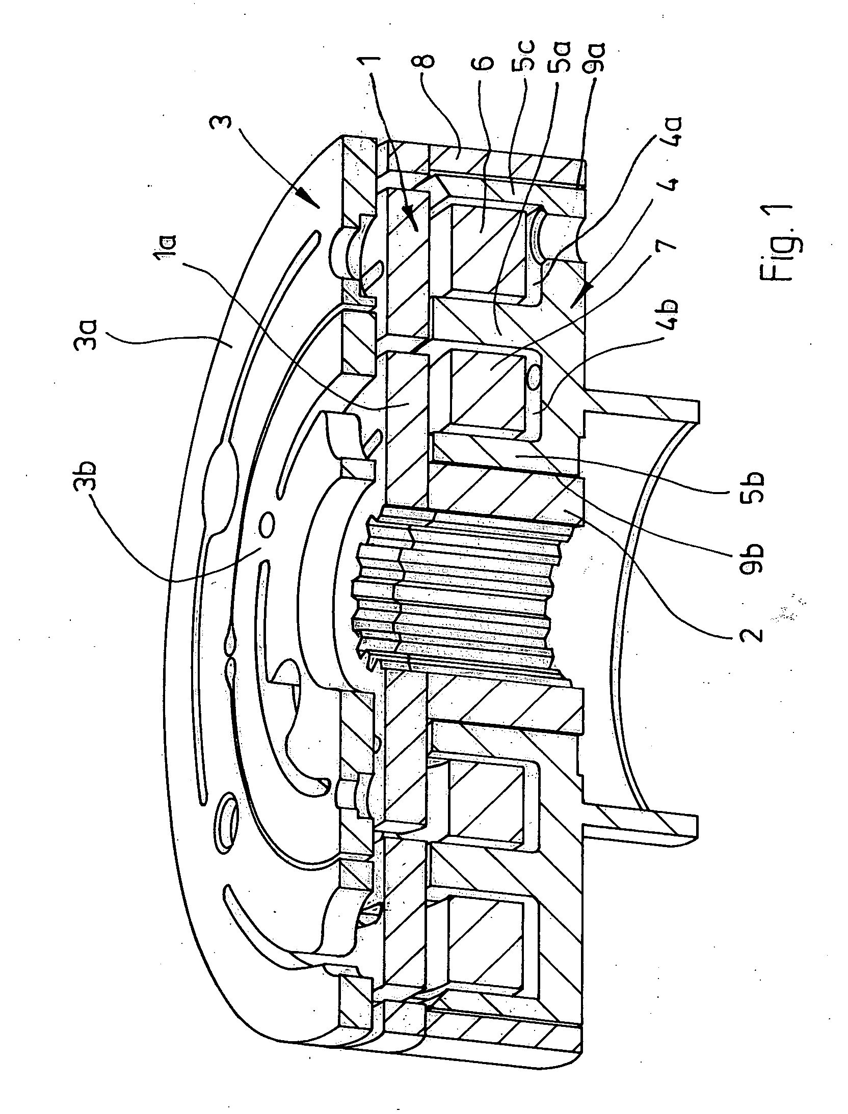
[0022]FIG. 1 depicts the important parts of a friction disk clutch. These include a rotor 1 which has an armature disk 3 spatially opposite it. The rotor has a shaft section 2 which is preferably only frictionally connected to a rotor disk 1a. At the radially outer edge, the rotor also comprises an annular web 8 which runs in the axial direction. The web 8 is preferably not integrally formed with the rotor disk 1a but attached to the rotor disk 1a, for example by welding, in particular laser welding. A magnet-surrounding body 4 is provided between the shaft section 2 and the web 8 and has two annular slot regions 4a, 4b which contain solenoids 6, 7.
[0023] In order to produce a two-stage friction disk clutch, the armature disk 3 is divided into two annular sections 3a, 3b which are drawn toward the rotor disk 1a when correspondingly supplied with power. If the solenoid 6 is switched on, the armature disk section 3a is drawn toward the rotor disk 1a. If the solenoid is switched on, t...
PUM
 Abstract
Description
Claims
Application Information