Controllable target cooling

a target and control technology, applied in the direction of electrical equipment construction details, lighting and heating equipment, laminated elements, etc., can solve the problems of increasing the number of screws required for a 2.5 m2.5 m target, the ruggedness of the target is questionable, and the price of the target and its backing plate is increasing for the larger size of the panel, so as to reduce the temperature differential

Inactive Publication Date: 2007-02-01
APPLIED MATERIALS INC
View PDF12 Cites 54 Cited by
  • Summary
  • Abstract
  • Description
  • Claims
  • Application Information

AI Technical Summary

Benefits of technology

[0011] Another aspect of the invention includes dividing the cooling holes into two interleaved groups and counter-flowing cooling liquid in the two groups of cooling holes, that is, in anti-parallel directions to thereby reduce the temperature differential across the target and its backing plate.

Problems solved by technology

The next generation is being developed to sputter deposit on panels having sides of greater than 2 m. This large size has introduced several problems not experienced in wafer fabrication equipment limited to sizes of about 300 mm in the most recent equipment.
Targets and their backing plates have become increasingly expensive for the larger sizes of panels.
However, the number of screws required for a 2.5 m×2.5 m target becomes very large.
Indium bonding can be used, but its ruggedness is questionable.
Autoclaving has been suggested, but this is a complex and expensive process.
The larger target sizes have also presented a challenge in uniformly cooling a larger area without unduly increasing the thickness of the target assembly.

Method used


Image

  • Controllable target cooling
  • Controllable target cooling
  • Controllable target cooling

Examples


Embodiment Construction

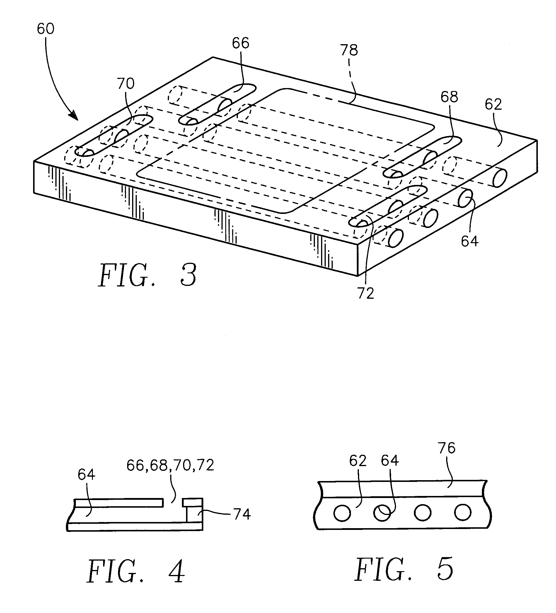
[0023] A backing plate 60 of one embodiment of the invention, very schematically illustrated in the orthographic view of FIG. 3 from the bottom, is formed in an integral metal plate 62 having lateral dimensions corresponding to the desired size of the backing plate 60, for example, greater than 2 m on a side for the planned next generation. A series of parallel cylindrical cooling holes 64 are bored to extend from one lateral side to the other of the metal plate 62 and parallel to the principal surfaces of the metal plate 62. Exemplary dimensions are a thickness for an aluminum plate of 33 mm and hole diameter of 12 mm. The hole boring over such a great distance may be achieved by gun drilling, that is, using a very long drill bit. In view of the long lengths, it is advantageous to drill holes from both sides which join in the middle. The cooling water or other liquid flows through the holes 64 to cool the backing plate 60 and hence the target tile affixed to the backing plate 60.

[...


PUM

PropertyMeasurementUnit
sizesaaaaaaaaaa
sizesaaaaaaaaaa
sizeaaaaaaaaaa

Abstract

A sputter target assembly particularly useful for a large panel plasma sputter reactor having a target assembly sealed both to the main processing chamber and a vacuum pumped chamber housing a moving magnetron. The target assembly to which target tiles are bonded includes an integral plate with parallel cooling holes drilled parallel to the principal faces. The ends of the holes may be sealed and vertically extending slots arranged in two staggered groups on each side and machined down to respective pairs of cooling holes on opposite sides of the backing plate in pairs. Four manifolds tubes are sealed to the four groups of slots and provide counter-flowing coolant paths.

Description

FIELD OF THE INVENTION [0001] The invention relates generally to sputtering apparatus. In particular, the invention relates to cooling of the sputtering target. BACKGROUND ART [0002] Sputtering is a well established technology in the fabrication in silicon integrated circuits, in which a metal target is sputtered to deposit target material onto the silicon wafer. Sputtering has also been applied to other uses, such as window coatings. In recent years, sputtering has also been applied for similar purposes as for silicon integrated circuits in the fabrication of flat panel displays, such as flat computer displays and large flat televisions and the like. Various types of flat panel displays may be fabricated typically including thin film transistors (TFTs) formed on large thin insulating rectangular substrates, often called panels, and including liquid crystal displays (LCDs), plasma displays, field emitters, and organic light emitting diodes (OLEDs). [0003] A conventional flat panel s...

Claims


Application Information

Patent Timeline
Patent Type & Authority Applications(United States)
IPC IPC(8): C23C14/32C23C14/00
CPCC23C14/3407Y10T29/49826H01J37/3497H01J37/3408C23C14/34
Inventor TANASE, YOSHIAKIINAGAWA, MAKOTOHOSOKAWA, AKIHIRO
Owner APPLIED MATERIALS INC
Why Eureka
Try Eureka