Laser head of a laser beam processing machine comprising alternating nozzles

a laser beam processing machine and laser beam technology, applied in laser beam welding equipment, welding equipment, metal-working equipment, etc., can solve the problems of affecting the processing efficiency of laser beam processing equipmen

Inactive Publication Date: 2007-02-01
DIEM REINHARD
View PDF10 Cites 15 Cited by
  • Summary
  • Abstract
  • Description
  • Claims
  • Application Information

AI Technical Summary

Benefits of technology

[0014] According to the invention, the housing carries a cap-shaped nozzle head. The cap may in this case also have the shape of a hemisphere, which is attached to the housing of the laser head and is matched to it. Alternating nozzles are provided on the inside of the nozzle head, and are held on the wall of the nozzle head so that they are rotatable about a rotation axis obliquely at an angle to the laser axis and can be introduced into the beam path of the laser beam. When a nozzle is changed, the nozzle respectively needed for the next method step can thereby be rotated into the beam pathwithout elaborate further adjustment and intervention being required on the nozzle head. The structure also then allows the automatic introduction of a nozzle, so that the set-up time is significantly reduced and the duration of unmanned operation is significantly extended.
[0017] The nozzle head in this configuration, for example as a stable hemisphere, protects against damage the nozzle disk or the nozzles which were always the first to suffer from collisions with the material being cut, owing to the nozzles being exposed.
[0020] According to a preferred refinement, the inlet channels provided in the housing for the working gas are arranged offset relative to the longitudinal axis of the beam space. This achieves controlled turbulence of the working gas as it is blown in.
[0021] In the space formed by the nozzle head following on from the housing, in order to prevent uncontrolled turbulence in the otherwise nonuniform space, the housing comprises an opening funnel which ends at a very short distance before the nozzle disk.
[0023] The invention makes it advantageously possible to carry out an automatic center determination by arranging a photodiode in the space surrounded by the cap-shaped nozzle head. It is used to collect light scattered from reflection surfaces of a nozzle used for the automatic center determination. This nozzle expediently has a larger measuring bore than the working nozzles and is positioned roughly below the laser beam. Under full load, the laser beam is moved relative to the measuring bore along a line onto the two opposite edge regions of the measuring bore. This is done by rotating the eccentric disk (x axis) and rotating the nozzle disk (y axis). When the respective edge region is reached, the scattered light appears and is recorded by the photodiode. This is the instant for storing the position. From the two positions, the average value is determined and the two opposite edge regions of the measuring bore are subsequently scanned along a line which is perpendicular to the previous line and passes through the center. Here again, the instantaneous position is recorded by the resolution of the photodiode when the scattered light is detected at the edge of the measuring bore, and the average value is formed therefrom. This average value then represents the circle center of the measuring bore, through which all the nozzle openings will then pass when the nozzle disk is rotated. The particular advantage of this adjustment is that the center determination can be carried out under a full load of the laser, since the laser beam behaves differently (“bends”) under different powers. The scattered light to be recorded by the photodiode results from contact of the laser beam with the material of the measuring nozzle, which may become damaged due to the contact. Yet since it is only a measuring nozzle, this damage can be tolerated. Owing to the structure of the nozzle head and the multiplicity of different nozzles, one can be obviated. This may be done by appropriate software.

Problems solved by technology

Furthermore, contamination of the very fine nozzle can also readily take place during processing due to material splashes, so that a nozzle change is also necessary for this reason.
This, however, produces errors in the focusing because the lens is no longer illuminated centrally.
The focus is therefore not optimal, which leads to inferior cutting results in laser cutting.
This in turn leads to a further deterioration of the focus.
This takes a relatively long time and interferes with the automatic process.
All these proposed solutions, however; are not satisfactory in use and require considerable equipment outlay for changing the nozzles with additional changer arms, as well as readjustment after each nozzle change.

Method used


Image

  • Laser head of a laser beam processing machine comprising alternating nozzles
  • Laser head of a laser beam processing machine comprising alternating nozzles

Examples


Embodiment Construction

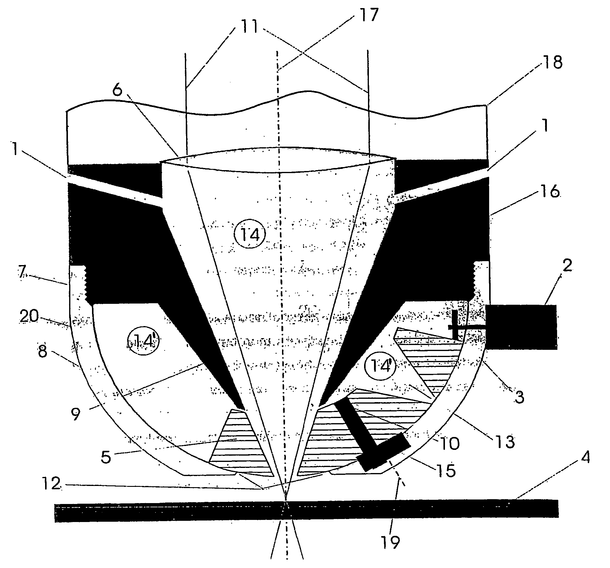
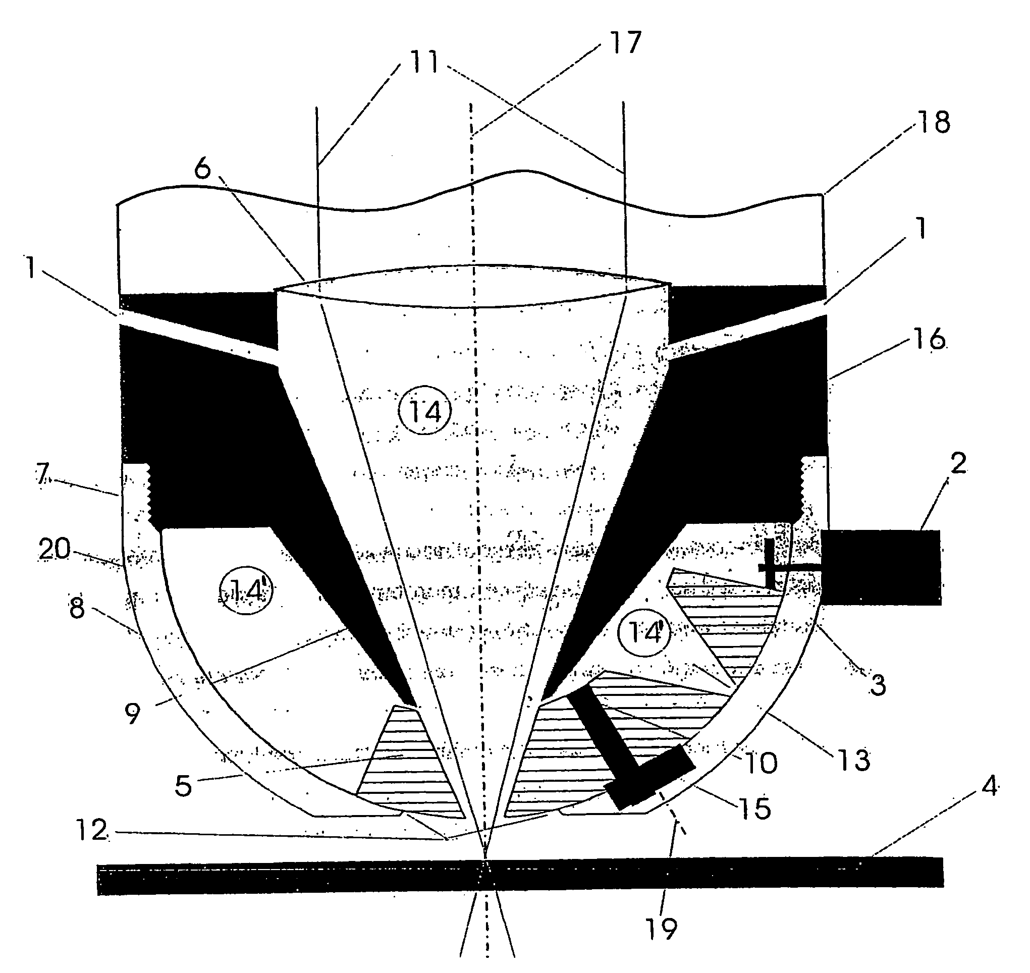
[0025] In a sectional representation, the FIGURE shows the nozzle-side end of a laser head 18 with the housing 16 and a hemispherical nozzle head 8 screwed onto the housing. In the known way, the laser beam 11 travels onto a lens 6 and is focused from there through the conical beam space 14 formed by the tip 9, symmetrically relative to the longitudinal axis 17 onto the material 4. The flow channels 1 opening into the beam space 14 are arranged for blowing in the working gas so that their axes do not intersect the longitudinal axis 17. A photodiode for detecting scattered light in the beam space 14′ may, for example, be arranged on the housing 16 on the horizontal surface above the tip 9 in the nozzle disk 5 on the left in the FIGURE. As mentioned above, the scattered light is generated by reflections on the edge of a nozzle 13 with enlarged hole diameter to be provided separately for this. The scattered light striking the photodiode starts the recording of the instantaneous positio...


PUM

PropertyMeasurementUnit
anglesaaaaaaaaaa
curvatureaaaaaaaaaa
thicknessesaaaaaaaaaa

Abstract

A laser head of laser beam processing machine which comprises a housing, in the interior of which a beam compartment and at the end thereof a nozzle for the laser beam and a working gas to exit are disposed. A dome-shaped nozzle head is provided on the housing and has alternating nozzles disposed on the interior. These nozzles are held rotatable about an axis of rotation and can be introduced into the beam path of the laser beam. The axis of rotation is located on an eccentric disk so that a one-off adjustment can be carried out while the nozzle head is exchanged. The nozzles on the nozzle plate can be exchanged without additional adjustment and thus also automatically, thereby avoiding the need for a complicated adjustment and handling during exchange of the nozzle.

Description

BACKGROUND OF THE INVENTION [0001] The present invention relates to a laser head in a laser beam processing machine having a housing, in the interior of which a beam chamber is arranged and at the end of which a nozzle is arranged for the exit of the laser beam and a working gas. [0002] Laser heads are widely known and are also referred to as welding heads, especially in the context of laser welding. In principle, however, such laser heads are used not only for welding but also to cut materials. [0003] The laser heads (welding heads) comprise in principle a concave mirror or a lens, which focuses the laser radiation. The converging beam is guided through a beam chamber inside a housing, which is closed by a nozzle. The beam emerges through this nozzle and is focused onto the processing site. The known laser heads generally also have additional bores through which a working gas is either introduced coaxially into the beam chamber or fed via additional bores through a separate nozzle ...

Claims


Application Information

Patent Timeline
Patent Type & Authority Applications(United States)
IPC IPC(8): B23K26/14
CPCB23K26/1482B23K26/1476
Inventor DIEM, REINHARD
Owner DIEM REINHARD
Why Eureka
Try Eureka