Liquid dispensing system with enhanced mixing

a liquid dispensing system and enhanced technology, applied in the field of dispensing apparatuses, can solve the problems of constant risk of contamination, limited application of devices, and difficult cleaning of devices, and achieve the effects of reducing cleaning chemical costs, facilitating cleaning, and reducing downtim

Inactive Publication Date: 2007-02-01
MILLIPORE CORP
View PDF45 Cites 8 Cited by
  • Summary
  • Abstract
  • Description
  • Claims
  • Application Information

AI Technical Summary

Benefits of technology

[0012] The single-use format allows for easy installation, pre-sterilization, and easy clean-up which will result in minimal downtime, significant cleaning chemical cost reduction, and greater ensured sterility. The shape and material of the reservoir are critical in maintaining product uniformity.

Problems solved by technology

While these fillers are popular due to their speed and accuracy, their application is limited, especially in the pharmaceutical field.
These devices are very difficult to clean, and typically must be disassembled to be sterilized.
Also, since the device actually contacts the fluid, contamination is a constant risk.
However, due to variances in the equipment and deformation of the discharge tube over time, these systems are less accurate than required for many applications.
The above mentioned apparatus can all be used to dispense single-phase fluids but all of the apparatus described suffer from one or more significant drawbacks when dispensing solids dispersed in liquid (suspensions) or droplets of one liquid suspended in another liquid (emulsions).
Either of these cases will result in poor content uniformity from one vial to the next during the final dispensing of the product.
In addition, it can be difficult to clean the process equipment that has contained suspensions or emulsions, resulting in labor intensive cleaning procedures and significant downtime to change from one batch to another.

Method used


Image

  • Liquid dispensing system with enhanced mixing
  • Liquid dispensing system with enhanced mixing
  • Liquid dispensing system with enhanced mixing

Examples


Embodiment Construction

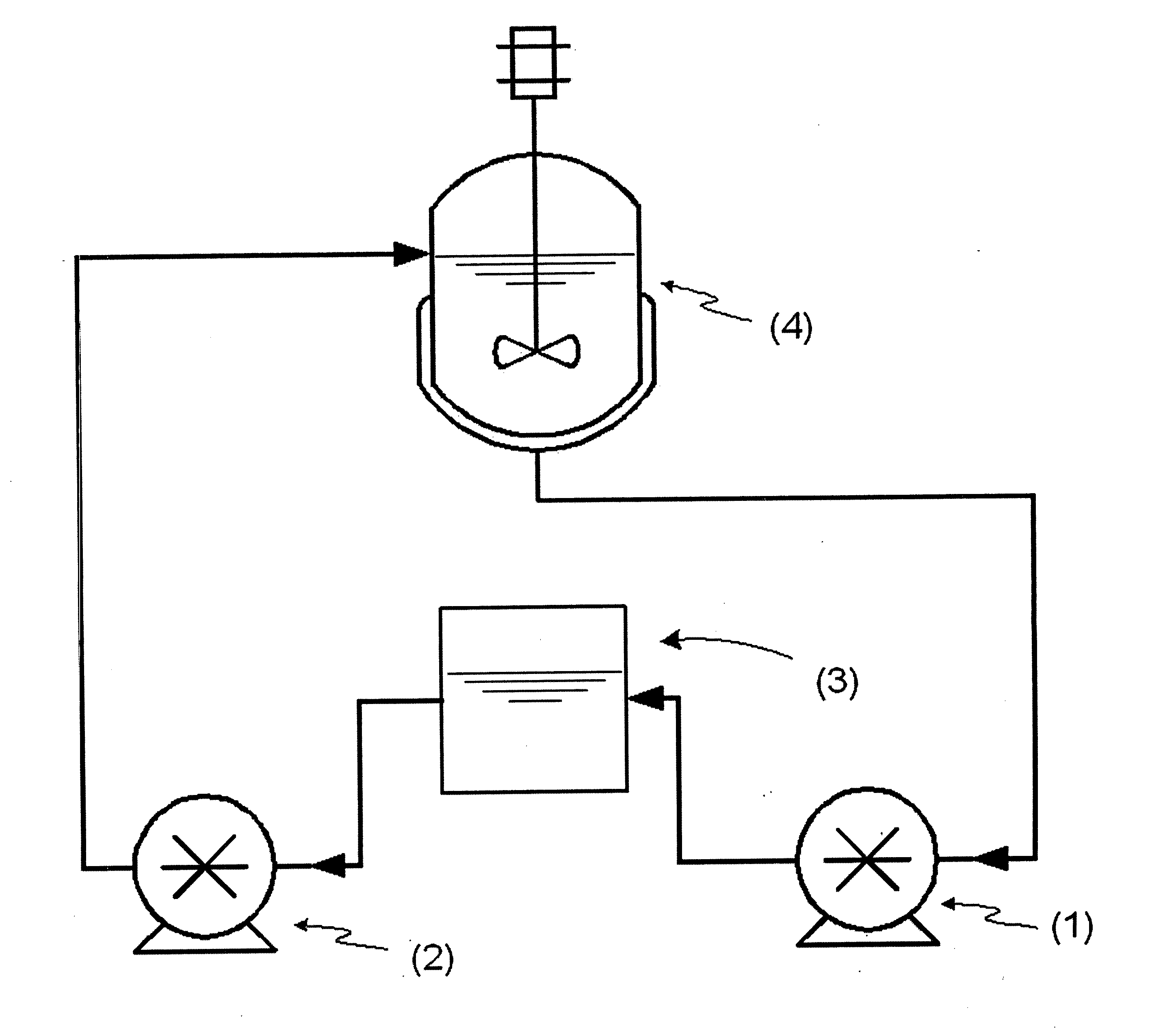
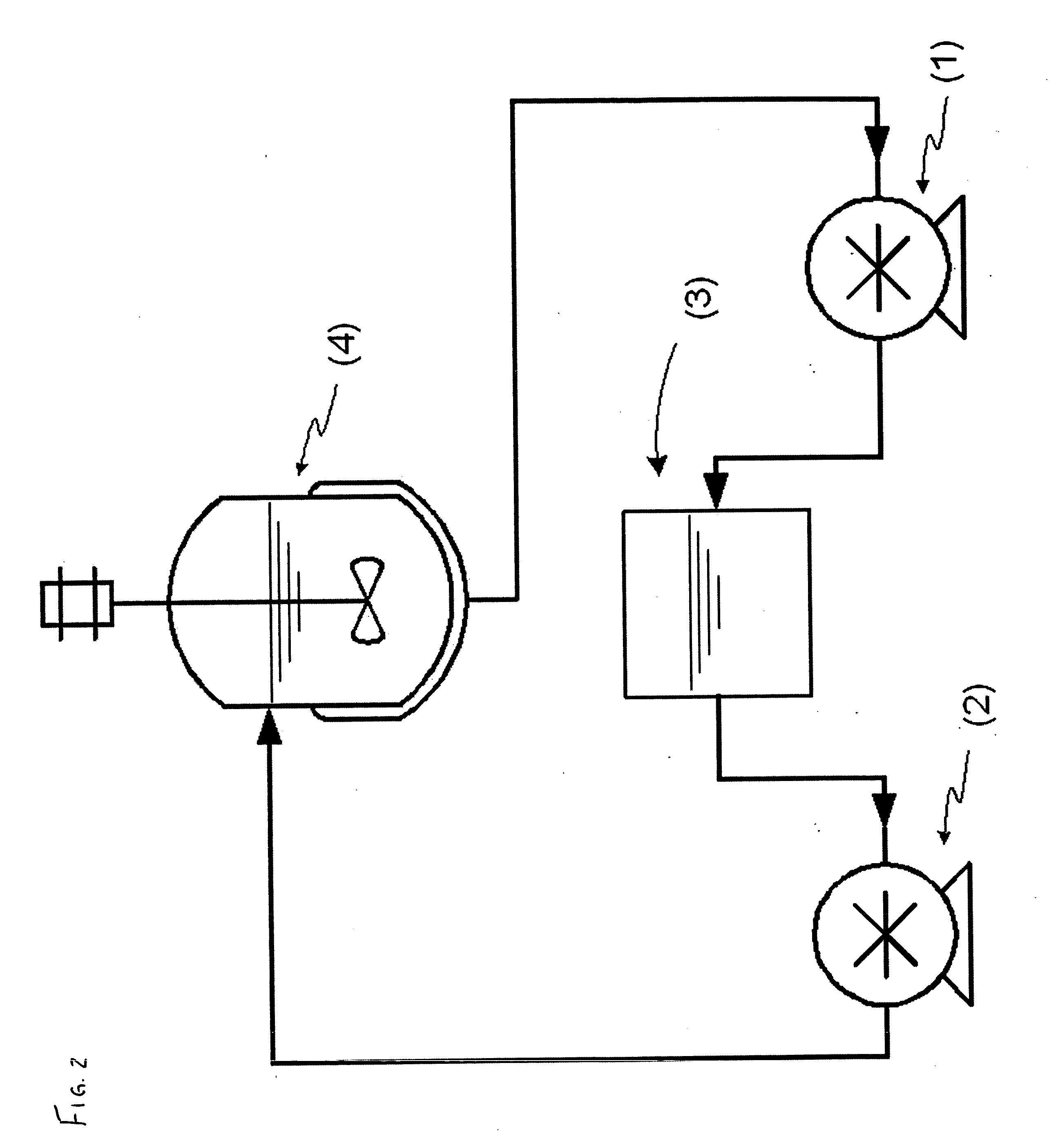
[0018] The dispense system described here consists of a single-use dispense cartridge and a hardware component onto which the dispense cartridge can be installed. The hardware system is described in the prior art (U.S. Pat. Nos. 5,680,960 and 5,480,063, the disclosures incorporated herein by reference). The present invention provides for a novel dispense cartridge and method that allows for the accurate dispensing of suspensions or emulsions.

[0019] Preferably the fluid reservoir section of the dispense cartridge is a pliable or flexible chamber or bladder, which expands and contracts to maintain a constant internal pressure. Disposable bag-like enclosures are particularly suitable. The tubing section of the dispense cartridge consists of flexible tubing such as silicone, polyethylene, or other elastomer or polymer based tubing attached together with plastic connectors made of materials such as polyethylene, polypropylene, or poly-fluorocarbons.

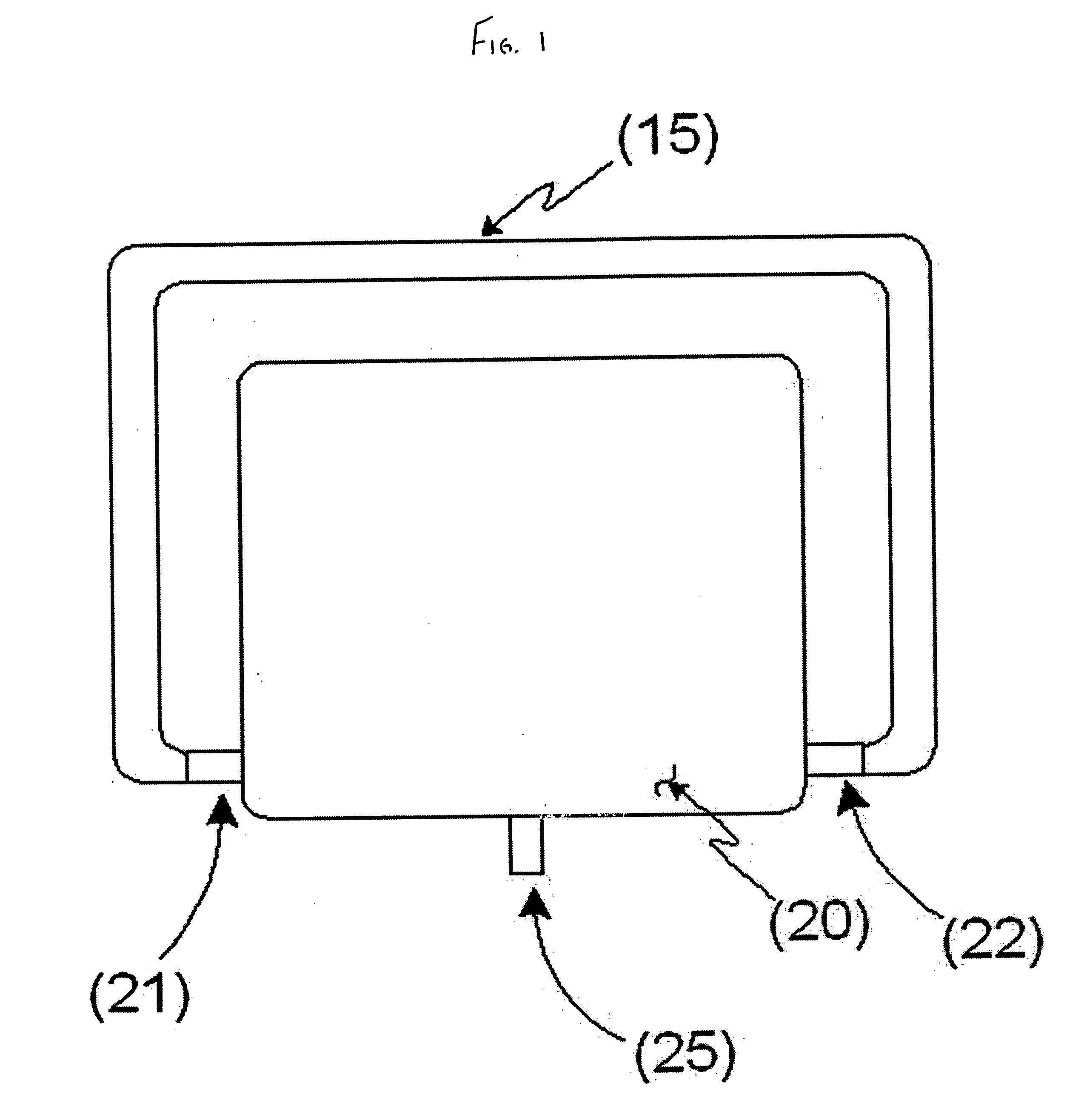
[0020]FIG. 1 shows one embodiment of ...


PUM

PropertyMeasurementUnit
volumeaaaaaaaaaa
speedaaaaaaaaaa
pressureaaaaaaaaaa

Abstract

A dispense apparatus and system for dispensing suspensions or emulsions. The system ensures uniformity of distribution of the dispersed phase within the continuous-phase liquid by moving the fluid through the dispense cartridge, such as with a continuous or pulsating flow. In one embodiment, peristaltic pumps are positioned upstream and downstream of the dispense cartridge, in fluid communication with and forming a single loop with a fluid source. Circulation between the fluid source and the dispense cartridge is maintained. In a second embodiment, a pump circulates fluid into and out of the dispense cartridge and is also in fluid communication with a fluid source such as with a pinch valve to allow proper filling of the dispense cartridge from the fluid source. In a third embodiment, a reversing pump is placed between the dispense cartridge and fluid source to continually or continuously pump fluid into and out of the dispense cartridge.

Description

BACKGROUND OF THE INVENTION [0001] There are various types of dispensing apparatuses for filling parenteral and opthalmic products into vials and containers. One such type is positive displacement fillers. These devices employ a cylinder and piston arrangement, which contacts and dispenses the fluid. Typically, fluid enters the cylinder as the piston is in its upward motion, which creates a vacuum into which the fluid enters through an inlet port. The downward motion of the piston expels the fluid through an outlet port. The process can then be repeated. Other embodiments of positive displacement fillers also exist, such as those using rotary pumps. [0002] While these fillers are popular due to their speed and accuracy, their application is limited, especially in the pharmaceutical field. These devices are very difficult to clean, and typically must be disassembled to be sterilized. Also, since the device actually contacts the fluid, contamination is a constant risk. [0003] Another ...

Claims


Application Information

Patent Timeline
Patent Type & Authority Applications(United States)
IPC IPC(8): B67D5/08B67D7/08
CPCB01F5/102B01F5/104B01F11/0071B01F11/0074B01F15/00123B01F15/00155G01F11/125B01F15/0201B01F15/0245B01F2003/0028B01F2003/0035B01F2215/0032B01F15/00883B01F23/023B01F23/024B01F25/51B01F25/52B01F31/651B01F31/65B01F35/20B01F35/2112B01F35/531B01F35/717611B01F35/71B01F2101/22
Inventor BELONGIA, BRETT M.SAUNDERS, ROBERT C.
Owner MILLIPORE CORP
Why Eureka
Try Eureka