Circuitry for supplying a load with an output current

a technology of output current and circuitry, which is applied in the direction of electric variable regulation, process and machine control, instruments, etc., can solve the problems disadvantage of comparatively high power dissipation, and change in current flowing through the load, so as to achieve efficient and interference-free operation of the load

Active Publication Date: 2007-02-01
INFINEON TECH AG +1
View PDF23 Cites 85 Cited by
  • Summary
  • Abstract
  • Description
  • Claims
  • Application Information

AI Technical Summary

Benefits of technology

[0019] It is an object of the present invention to provide a circuitry for efficient and interference-free operation of a load, which converts electrical energy into another form of useful energy.
[0021] It is the central idea of the present invention that an operation of a load converting electric energy into another form of energy, so that the useful power provided in the form of useful energy is substantially proportional to the output current flowing through the load, can be obtained in a particularly favorable way when a piezo transformer provides the output current. It has been shown that by using a piezo transformer, a particularly precise adjustment or regulation of the output current to a predetermined value is possible, wherein a high flexibility exists with regard to tapping a feedback quantity when using a piezo transformer, since both an input current of the piezo transformer and an auxiliary signal tapped at the auxiliary output of the piezo transformer represent a measure for the output current, which can be used for regulating. Further, due to the high Q, a piezo transformer allows a suppression of harmonics, so that the output current substantially only has a base frequency. Thereby, interference of adjacent circuitries by the inventive circuitry is avoided or minimized, respectively.
[0022] Further, a circuitry using a converter means for generating an alternating current signal from energy of an energy source, as well as piezo transformer receiving the alternating current signal on the input side, has a particularly high efficiency. By appropriate control or regulation of the converter means, it can be ensured that the converter means supplies approximately exactly that energy to a piezo transformer, which is consumed by the load connected to the output of the piezo transformer. Switching losses in the converter means can be kept low, and losses in the piezo transformer itself are very low due to the typically high Q of a piezo transformer. By using the inventive circuitry, adjustment of the current is performed by the electrical load and not, as in common practice, by dissipation. Thus, power dissipation of the inventive circuitry is low, which, on the one hand, reduces the power consumed on the input side and, on the other hand, minimizes objectionable heat built-up.
[0023] Further, a piezo transformer allows to replace the conventionally required several passive devices with only one device, the piezo transformer itself. The piezo transformer can be kept low and small in its structural height, so that there is an advantage with regard to the required structural volume of the inventive circuitry compared to conventional circuitries. This facilitates the realization of an inventive circuitry with a given housing.

Problems solved by technology

The disadvantage of such approaches is a comparatively high power dissipation and the fact that the current flowing through the load also changes with changing input voltage.
Analog regulators, such as linear regulators, have the advantage of a very low interference emission, but again have the disadvantage of comparatively high power dissipation.
However, resonant flyback converters are more expensive in terms of circuit engineering, since they require additional resonance elements.
The inductance makes the regulator bulky and expensive, respectively, both in size and costs.
A flyback converter as hard-switching regulator with a switch according to FIG. 1a or 1b has the disadvantage that a current with high frequency is interrupted towards the input, so that a high-frequency input interference-spectrum is significant and has to be suppressed with additional filtering effort (at least in interference-sensitive applications).
Further, converters or regulators according to FIG. 1A or 1B for driving constant current loads, such as light-emitting diodes (LEDs) have the disadvantage that a filter capacitor Cout on the output side and a fast rectifier diode Dout have to be used to generate a voltage across the light-emitting diodes (LEDs) as a constant current load (KS).
Since light-emitting diodes (LEDs) have no high reverse disruptive strength, the shown arrangement is usually not practicable.
Further, the Buck converter has the additional disadvantage that the input voltage Uin always has to remain higher than the sum of forward voltages of the light-emitting diode of the LED chain.
A reverse disruptive strength of the LED chain would additionally be sufficient to operate the light-emitting diodes (LEDs) in reverse direction, since a voltage would be equal to zero in an on state of the switch S. However, the circuit or circuitry 300 has the disadvantage that it is not short-circuit-proof, so that in the case of a short circuit across the LED chain, the input source (providing the input voltage Uin) is not protected from overcurrent.
A corrective is provided, for example by an additional limiting resistor in an input circuit, which causes, additionally, increased losses, even during normal operation.
Alternatively, a fast fuse can be used, which again causes additional costs and irreversible failure in the case of a short circuit.
Further, all flyback converters shown with regard to FIGS. 1a, 1b, 2 and 3 have the disadvantage that they have to be regulated by a feedback of the output current or output voltage to an approximately constant output power and thus to a constant current in the light-emitting diodes (LEDs) or other electrical loads.
Additionally, the boost converter (for example the converter according to FIG. 3) has the disadvantage that additional elements for damping short-term overvoltages (for example for dealing with a load drop or load dump, respectively) are required in vehicle networks in order to avoid an overload at the electrical loads (for example at the LED chain).

Method used


Image

  • Circuitry for supplying a load with an output current
  • Circuitry for supplying a load with an output current
  • Circuitry for supplying a load with an output current

Examples


Embodiment Construction

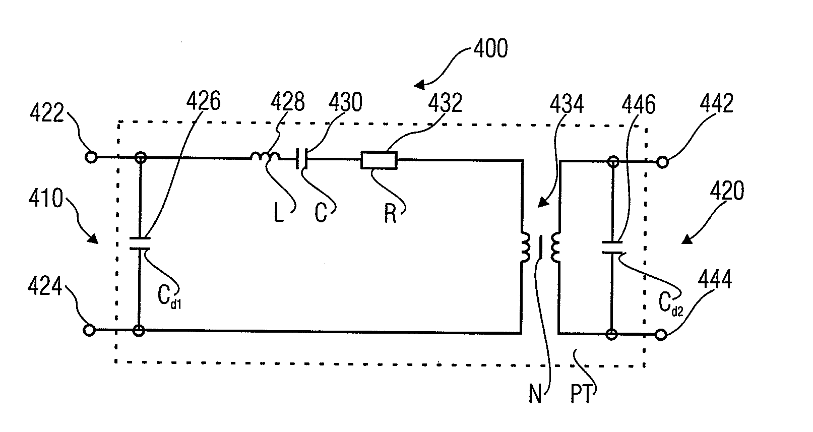
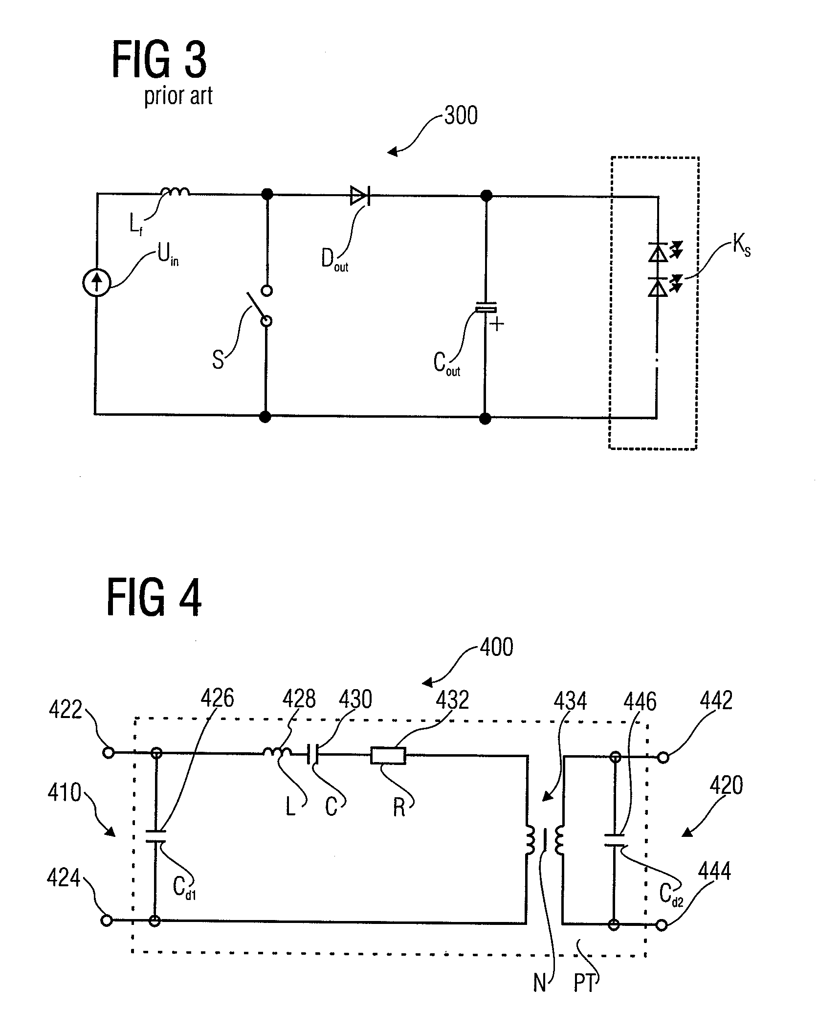
[0056]FIG. 4 shows an equivalent circuit diagram of a piezo transformer for usage in an inventive circuitry. The piezo transformer according to FIG. 4 is designated by 400 in its entirety. The piezo transformer 400 (in the following also designated as piezo trafo) comprises an input 410 and an output 420, which can be, for example, galvanically separated (but not necessarily have to be so). The input 410 has two input terminals 422, 424. An input capacitance 426, which is also designated by Cd1, is connected between the first input terminal 422 and the second input terminal 424. Further, the piezo transformer 400 has a series resonant circuit, consisting of an inductance 428 (also designated by L), a capacitance 430 (also designated by C) and a resistor 432 (also designated by R). The series resonant circuit 428, 430, 432 (RLC) is connected in series to an input of a transformer 434 between the first input terminal 422 and the second input terminal 424, as can be seen from FIG. 4. A...


PUM


Abstract

A circuitry comprises a converter means for generating an alternating current signal from an energy from an energy source, a piezo transformer with an input and an output, wherein the input of the piezo transformer is electrically coupled to the converter means, to receive the alternating current signal as an excitation on the input side from the converter means, and wherein the output of the piezo transformer is designed to provide an output current, and a load, which is coupled to the output of the piezo transformer, so that output current flows through the same. The load is designed to convert at least part of the electrical energy supplied by the output current flowing through the load into another form of energy. The load is further designed such that a useful power provided in the form of useful energy is substantially proportional to the output current. The circuitry is designed to adjust the output current to a predetermined value. The described circuitry allows the supply of a load with particularly high efficiency, low interference emission and good regulation characteristics.

Description

CROSS-REFERENCE TO RELATED APPLICATION [0001] This application claims priority from German Patent Application No. 102005023687.1, which was filed on May 23, 2005, and is incorporated herein by reference in its entirety, and from German Patent Application No. 102006022819.7, which was filed on May 16, 2006 and is incorporated herein by reference in its entirety. BACKGROUND OF THE INVENTION [0002] 1. Field of the Invention [0003] The present invention relates generally to a circuitry for supplying a load with an output current, particularly to a control device for constant current loads with piezoelectric transformer. [0004] 2. Description of the Related Art [0005] In many technical applications, it is required to supply electric loads, such as light-emitting diodes, fluorescent lamps or accumulators with a current. [0006] Present simple approaches for operating such loads are, for example, series resistors. Thus, series resistors are frequently used, particularly in the context of li...

Claims


Application Information

Patent Timeline
Patent Type & Authority Applications(United States)
IPC IPC(8): G05F1/12
CPCH02M7/537H05B33/0848H05B33/0821H05B33/0815H05B45/14H05B45/39H05B45/42
Inventor RADECKER, MATTHIASLENZ, MICHAEL
Owner INFINEON TECH AG
Why Eureka
Try Eureka