Integrated polarizer/optical film with a wire grid structure and a manufacturing method thereof

Inactive Publication Date: 2007-02-01
TAIWAN TFT LCD ASSOC +7
View PDF18 Cites 14 Cited by
  • Summary
  • Abstract
  • Description
  • Claims
  • Application Information

AI Technical Summary

Benefits of technology

[0017] Therefore, it is a primary object of the present invention to provide an integrated polarizer/optical film with a wire grid structure and a manufacturing method thereof, that primarily adopts a system of assembly model to overcome the overall poor match of optical effect of the traditional polarizer and brightness-enhancing film, causing an overall decrease in the light transmittance and having its polarization achieved only via the polarizing film. The present invention rearranges the polarization and light transmittance level of different films to produce an overall polarization and light transmittance level higher than those of the polarizer accompanied with the brightness-enhancing film. The present invention also reflects light and uses multi-layer polarizing film optics design to avoid the disadvantages of wide vi

Problems solved by technology

At present, the transmittance of the current iodine polarizers is up to 44% to 46%, and has approached a level that makes further improvement of the light transmittance level difficult.
The main disadvantages of O iodine polarizers are as follows: (1) O iodine polarizers have acute light loss in wide viewing situations, so O iodine polarizers need to be matched with a wide-viewing angle film to achieve high contrast; (2) O iodine polarizers do not work well in conditions with high temperatures or high humidity; (3) the polarizer mechanical properties of O iodine are not strong, so O iodine polarizers must have a protective film pasted onto it to strengthen its outside surface; (4) O iodine polarizers can only be pasted onto the outside of a monitor.
The mechanical properties, the temperature and humidity of the polarizer are p

Method used


Image

  • Integrated polarizer/optical film with a wire grid structure and a manufacturing method thereof
  • Integrated polarizer/optical film with a wire grid structure and a manufacturing method thereof
  • Integrated polarizer/optical film with a wire grid structure and a manufacturing method thereof

Examples


third embodiment

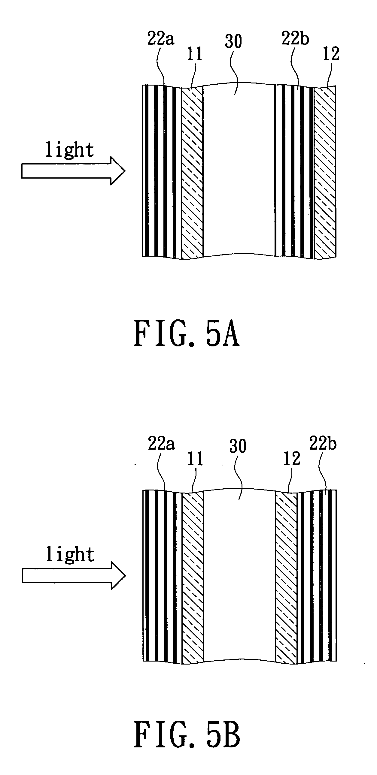
[0062]FIG. 5C shows third embodiment in accordance with the FIG. 5A of the present invention. In this embodiment, the far side of the light source of the first substrate 11 and the second substrate 12 are sitting upon the integrated polarizer / optical film 22a and 22b individually.

[0063]FIG. 5D shows a forth embodiment in accordance with FIG. 5A of the present invention. In this embodiment, the cross side of the plurality of fluid media 30 of the first substrate 11 and the second substrate 12 sits upon the integrated polarizer / optical film 22a and 22b individually.

[0064] The combination of the integrated polarizer / optical film has various forms depending upon the use of different materials. FIG. 5E shows an embodiment using two substrates using different materials in accordance with the present invention. This embodiment comprises the first substrate 11, the second substrate 12 and the plurality of fluid media 30 filled in between. The cross side of the light source of the first sub...

second embodiment

[0065]FIG. 5F shows two substrates applied for different materials in accordance with the present invention. In this embodiment, the cross side of the light source of the first substrate 11 sits upon the integrated polarizer / optical film 22a. The far side of the light source of the first substrate 12 sits upon the integrated polarizer / optical film 24a. The cross side of the light source of second substrate 12 sits upon the integrated polarizer / optical film 22b.

[0066]FIG. 5G shows a third embodiment of two substrates used for different materials in accordance with the present invention. In this embodiment, the cross side of the light source of the first substrate 11 sits upon the integrated polarizer / optical film 22a. The far side of the light source of the second substrate 12 sits upon the integrated polarizer / optical film 24a. The far side of the light source of second substrate 12 sits upon the integrated polarizer / optical film 22b.

[0067]FIG. 5H shows a forth embodiment of two s...

fifth embodiment

[0068]FIG. 5I shows two substrates used for different materials in accordance with the present invention. In this embodiment, the cross side of the light source of the first substrate 11 sits upon the integrated polarizer / optical film 22a. The cross side of the light source of the second substrate 12 sits upon the integrated polarizer / optical film 22b. The far side of the light source of second substrate 12 sits upon the integrated polarizer / optical film 24b.

[0069] The integrated polarizer / optical film of the present invention is disposed on two sides of the substrate. Thereby, it is possible to view the monitor from two sides. FIGS. 5J to 5L show an integrated polarizer / optical film applied with two substrates and a part between the two sides of the substrate in accordance with the present invention.


PUM


Abstract

An integrated type optical film with a wire grid polarizer structure and a manufacturing method thereof solves the optical matching problem of conventional optical film and integrates an optical effectiveness with all layers by using non-linear optical theory to redistribute integral polarizing efficiency and transmittance in all layers. The integrated type optical film includes two types of polarizers, a reflective type wire grid polarizer and an absorbing type polarizer. The reflective type wire grid polarizer can reflect an incident polarizing light parallel with a metal grid thereof, and transform and transmit polarizing light perpendicular to the polarizer with secondary transmitting efficiency, so that multi-layered structures are integrated into a polarizer with high polarizing efficiency, high transmittance and light-reflective efficiency.

Description

BACKGROUND OF THE INVENTION [0001] 1. Field of the Invention [0002] The present invention relates to an integrated polarizer / optical film with a wire grid structure and a manufacturing method thereof, and more particularly, to an integrated polarizer / optical film structure that can both reflect and absorb light. The polarizer / optical film structure utilizes nonlinear optical theory to redistribute integral polarizing efficiency and transmittance to all layers of the polarizer / optical film structure and a manufacturing method thereof. [0003] 2. Description of Related Art [0004] Currently, polarizer / optical film is applied to all kinds of goods, for example, polarizing film, wide-viewing angle film or brightness enhancement film for display screens. It can also used for polarizing optical microscopes, sunglasses, objects used to create shade, display screens, and lighting. [0005] Liquid crystal displays (hereinafter referred to as LCDs) need polarizer / optical film. LCDs use two-pieces...

Claims


Application Information

Patent Timeline
IPC IPC(8): G02F1/1335
CPCG02B5/3058G02F2001/133548G02F1/133528G02F1/133548
Inventor JENG, YUE-SHIHCHEN, YUH-SHYANGLIU, WEI-CHIHWANG, TSUNG-HSIUNGWU, YU-HSUNCHIEN, WEI-YI
Owner TAIWAN TFT LCD ASSOC
Why Eureka
Try Eureka