Device for precise distance measurement

a technology of precise distance measurement and device, applied in the direction of distance measurement, instruments, surveying and navigation, etc., can solve the problems of difficulty in developing precise distance measurement techniques for 100 meters with reflected lasers and other radiants, difficulty in resolution of obtained, and inability to meet the requirements of measurement accuracy,

Inactive Publication Date: 2007-02-01
KLOZA MARIUSZ
View PDF3 Cites 44 Cited by
  • Summary
  • Abstract
  • Description
  • Claims
  • Application Information

AI Technical Summary

Benefits of technology

[0015] The pulse receiver includes a radiant energy detector and a sampling circuit that is responsive to a sampling control input and provide an output. The sampling circuit is in communication with the radiant energy detector and is configured to provide at the output a measure of radiant energy at the detector. The pulse transmitter transmits a beam of repeating pulses having a substantially stable period of oscillation. The transmitter includes a trigger control input and an emitter circuit that is responsive to this input.
[0016] The scanning module is configured to be in communication with the pulse receiver and controls the sampling control input to record radiant energy detected by the receiver over a time window

Problems solved by technology

Development of techniques for precisely measuring shorter distances (e.g., <100 meters) with reflected laser and other radiant has been technically challenging, however, because of the relative speed of electromagnetic radiation as compared to digital processing capabilities.
More specifical

Method used


Image

  • Device for precise distance measurement
  • Device for precise distance measurement
  • Device for precise distance measurement

Examples


example

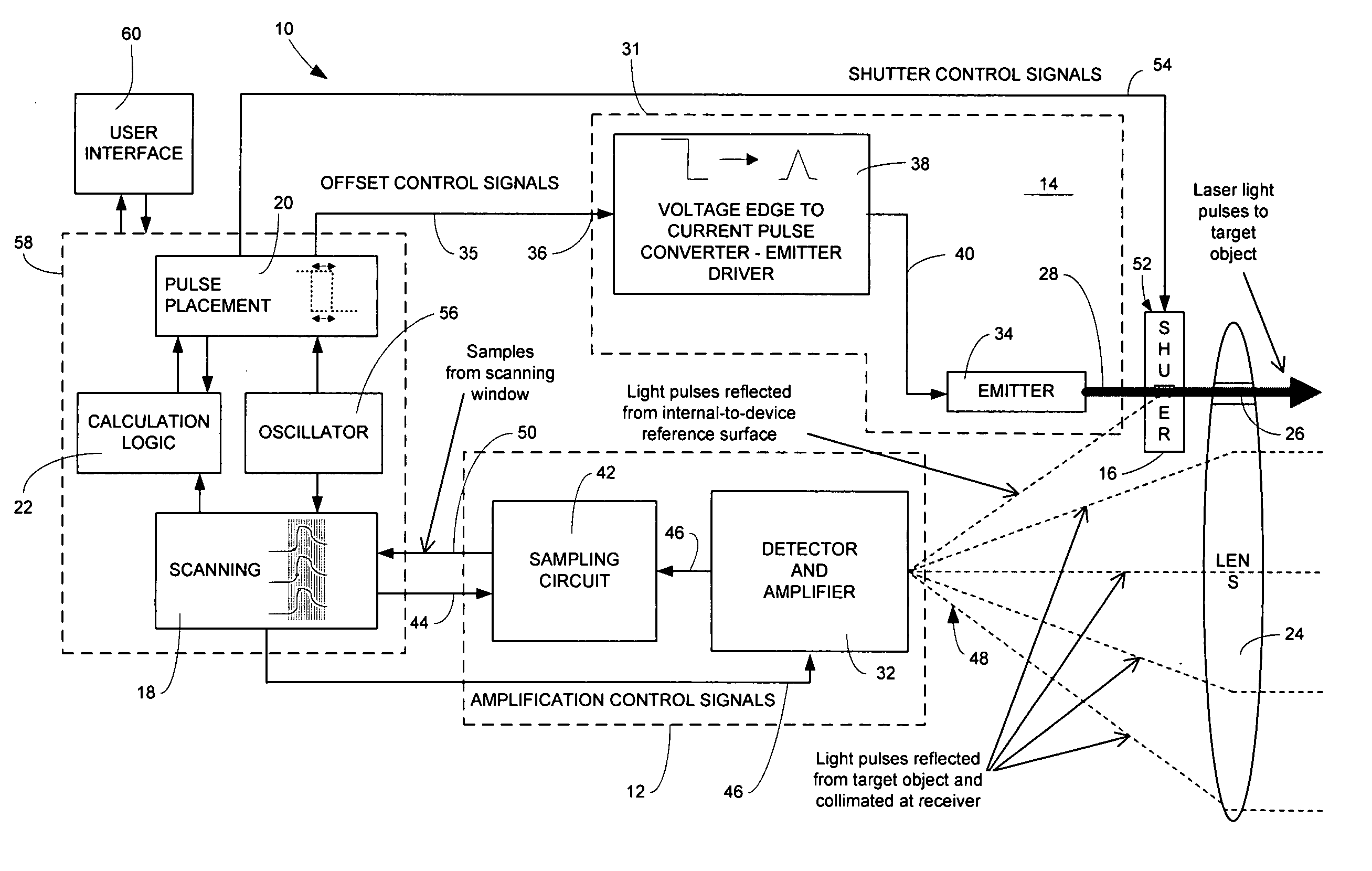
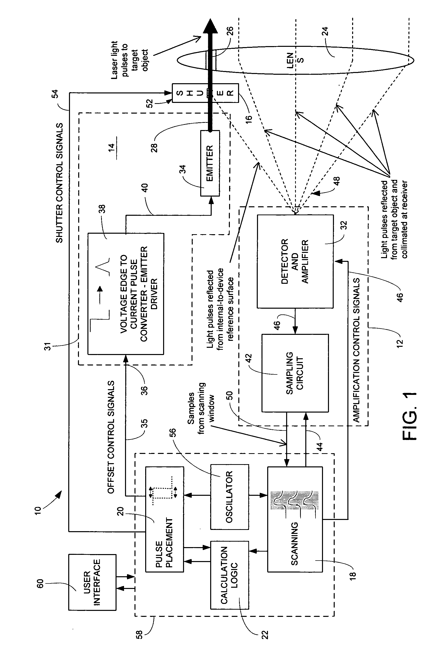
[0059] A laser measuring device 110 was constructed according to an embodiment of the present invention. A schematic diagram of laser device 110 is presented in FIG. 6. Measuring device 110's major parts or elements include a pulse detector circuit 132, a sampling circuit 142, a laser diode 134, a reference surface 116, a microcontroller (e.g., TMS320F2801) 158 and a power supply 153. Device 110 also includes optics in the form of a lens 124 with an exit region 126 and a shutter mechanism 152 for selectively directing a pulse series 128 towards a target object. Operably connected to microcontroller 158 are user interface components: display 160A, keys and switches 160B and buzzer 160C. An associated power system 153 includes a battery power source 155, a main voltage supply 157 and an electronically adjustable higher-voltage supply 159 for adjusting photodiode amplification.

[0060] Both detector circuit 132 and laser emitter 134 are positioned for interaction with optics 124. Detect...


PUM


Abstract

An electronic method for distance measurement based on pulsed laser time-of-flight is provided. The method comprises generating a wave of outgoing radiant energy pulses having a substantially stable period for providing a wave of pulses reflected from a target object and then measuring reflected energy from the pulse wave over a scanning time window. The scanning time window is shorter than the laser pulse time-of-flight to and from the measurement target. An offset between outgoing pulses and the scanning window is adjusted to capture reflected pulses at desired positions within the scanning window for selected conditions including when the outgoing wave is reflected from a reference surface and when the outgoing wave is reflected from the distance target. Distance is then calculated according to the offset and reflected energy data recorded for the selected conditions.

Description

CROSS-REFERENCE TO RELATED APPLICATION [0001] This application claims priority from U.S. Provisional Applications for Patent No. 60 / 698,697 filed on 13 Jul. 2005.FIELD OF INVENTION [0002] This invention pertains to distance measuring methods, circuits and devices based on reflected electromagnetic wave energy. COPYRIGHT NOTIFICATION [0003] Portions of this patent application contain materials that are subject to copyright protection. The copyright owner has no objection to the facsimile reproduction by anyone of the patent document, or the patent disclosure, as it appears in the Patent and Trademark Office. BACKGROUND OF THE INVENTION [0004] The advantages of accurately and precisely measuring distance by energy reflection are self evident in that the need to physically traverse the distance with a tape or a counter is eliminated. The concept is to measure the time required for an incident of radiant energy to travel to and then from a target point. Based on this time of flight and ...

Claims


Application Information

Patent Timeline
IPC IPC(8): G01C3/08
CPCG01S7/4811G01S7/486G01S17/10G01S7/497G01S7/4868
Inventor KLOZA, MARIUSZ
Owner KLOZA MARIUSZ
Why Eureka
Try Eureka